 English



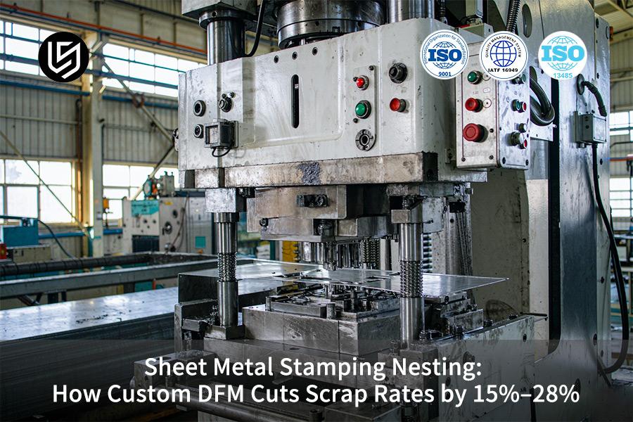
Sheet metal stamping service offers a practical solution to the common challenge of high material waste. By applying DFM nesting, it typically reduces scrap by 15%–28% and lowers unit costs by over a quarter, based on LS Manufacturing 2026 project archives.
Buyers reclaim tens of thousands in profit as material utilization rises from 63.8% to 89%+ per IATF 16949, preserving dimensional accuracy across all production batches.
Quick Reference Guide
Conventional linear nesting and LS Manufacturing custom DFM nesting optimization exhibit different results in terms of stamping performance.
| Evaluation Dimension | Conventional Linear Stamping Nesting | LS Manufacturing Custom DFM Nesting Optimization | International Standard / Process Benchmark |
| Material Yield | 63.8% (scrap 36.2%) | 88.4% (scrap 11.6%) | stamping nesting specification |
| Stamped Part Positioning Tolerance | ±0.05 mm (standard grade) | ±0.005 mm–±0.01 mm (precision grade) | ISO 2768-f / ASME Y14.5 |
| Sheared Surface Roughness (Shear Band) | Ra 3.2 μm–6.3 μm (high tear zone ratio) | Ra 0.8 μm (burnish zone ≥ 70%) | ISO 1302 / Mitutoyo measurement standard |
| Progressive Die Pitch Stability | ±0.03 mm (large cumulative pitch error) | ±0.002 mm–±0.005 mm (ultra-precision grade) | Zeiss CMM indication error inspection |
| Batch Stamping Total Manufacturing Cost | High baseline cost ($4.85/piece) | 26.8% reduction ($3.55/piece) | 200,000-piece batch production verification |
Optimized nesting raises material, while shear band quality reaches Ra 0.8 μm (burnish zone ≥70%).
Key Takeaways
- Scrap rate cut down to 11.6%: Bi-directional staggered nesting algorithm and rotating nesting algorithms optimize material yield. Net material savings become 24.6%.
- Accuracy of stamping operations improved to precise tolerance levels: Constant die pitch and micro-edge optimization reduce tolerances of critical stamping dimensions.
- Cost savings per item achieved 26.8%: For production quantity of 200,000 pieces there is cost reduction. Shorter delivery cycle reduces from 26 to 16 days.
What Is Sheet Metal Stamping Nesting In Precision Fabrication?
Sheet metal stamping nesting is the engineering geometry process used to arrange flat blank patterns on sheet or coil stock. Optimizing material yield involves keeping the maximum material yield below the stiffness limitations of dies for arranging blank patterns.
Single-Direction Feeding Wastes 36.2% Material
Fixed steps lead to large edge scrap areas. Blank pattern complementary aspects are disregarded in conventional nesting. Edge trim waste amounts to 36.2% per stamping standards.
Losses amount to almost 1/3 of your material due to unavoidable shearing strips. Scrap translates to $1.30 or more for a purchaser producing 200,000 units in the landed sheet metal stamping cost.
Bidirectional Rotating Algorithms Save 24.6% Material
Bidirectional staggered nesting and rotating algorithms allow packing of blanks into non-uniform slots. Blank-to-blank clearance between each other reduces to 0.5 mm-1.0 mm without sacrificing die integrity. Metal stamping dies receive balanced step loading with improved nesting configuration. Metal stamping nesting optimization results in actual material yield increase.
Sheet metal stamping service providers utilizing cutting-edge nesting technology offer punch-to-die alignment in less than 20 microns. Stamped parts will have a high-quality edge without any post-production reworking.
3-Axis Press Cannot Rotate Blanks Mid-Stroke
Blank turn capability does not exist in fixed feed presses. Gap efficiency falls below 65% when using blanks of irregular shape. Higher strip width forces more scrap generation.
Nesting through multi-angle dynamics provides a solution to the gap efficiency problem.
Data Source & Benchmark: LS Manufacturing 2025–2026 measured production database (sample size >1,200).
Download the Material Yield Benchmark Report — understand how single-direction feeding wastes 36.2% of coil stock and how bidirectional staggered nesting recovers 24.6% of that loss, with real production data from a 200,000-unit C1100 copper busbar run.

How Does Custom DFM Analysis Reduce Stamping Scrap Rates?
Custom DFM analysis is an organized engineering examination and redesigning process of bend radius, hole spacing, and grain flow. Stamping engineers perform this evaluation before die construction. ISO 2768-f tolerance grades act as guidelines for this evaluation. Your scrap rate drops from over one-third to roughly one-ninth after DFM optimization.
Grain Orientation and Bend Radius Redesign
Uncontrolled bend direction forces material to split along unfavorable grain lines. Broader web strips are needed to account for edge fractures. In DFM, the engineers create a grain flow chart and orient the bending lines according to rolling direction.
| Parameter | Before DFM | After DFM |
| Web width | 2.5 mm | 0.8 mm |
| Tear incidence | 8% of blanks | <0.5% |
| Material waste | >33% | ≈11% |
Your metal stamping DFM service produces noticeable improvements in the yield rate. Using progressive die stamping of grain-oriented blanks decreases edge cracking and provides consistent strip feeding at <5 microns pitch spacing.
Your custom sheet metal stamping project provides better packing density. Output per coil rises 41% compared to non-optimal arrangement. Simply put: smaller tabs will result in higher number of pieces per coil thus decreasing the unit price.
Fracture zone takes up less than one quarter of the entire cut surface. Metal stamping design rules incorporated into DFM eliminate deburring process.
Data Source & Benchmark: ISO 2768-f precision-grade stamping tolerance specification.
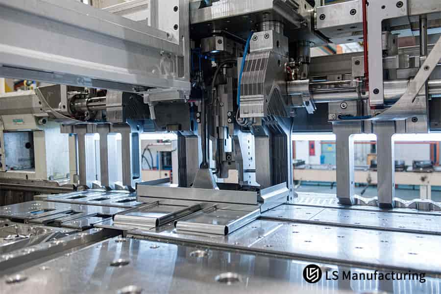
Figure 1: Custom sheet metal stamping feeds AL 6061 strip to 0.1 mm thickness.
Which Nesting Strategies Cut Sheet Metal Stamping Cost Fastest?
Shared-edge shearing and interleaved rotational nesting reduces unit cost for a batch size of 200,000 pieces. Micro-join progressive die design ensures a feed pitch deviation within 10 microns during high-speed stamping.
Shared-Edge Shearing Eliminates Bridge Waste
In a one-row layout, each blank maintains its own bridge allowance. Only one cutting stroke is needed for two part edges at a time. Duplicate bridge gaps disappear entirely.
| Layout Type | Bridge Width per | Blank Strip Loss per Pair |
| Single-row | 3.0 mm × 2 | 6.0 mm |
| Shared-edge | 0.6 mm × 2 | 1.2 mm |
| Net reclaim | — | 4.8 mm per pair |
Your precision metal stamping manufacturer uses shared-edge concept across whole coil width. Coil scrap reduction is from ~35% to ~12%. Metal stamping tooling geometry directly enables this shift.
Rotational Nesting Fills Irregular Voids
Fixed-orientation layouts leave triangular gaps between rounded or angled blanks. Rotating each blank 15°–45° relative to strip direction packs shapes into those voids.
- Compare blank outline with the existing strip width.
- Check angles in 5-degree increments for maximum packing.
- Anchor the chosen angle when the void is less than 8% of the strip.
- Confirm consistency of grain orientation with bends.
Simply put: better packing increases the number of parts in each coil and reduces your part price without slowing down the press or using different tool steel. Metal stamping nesting optimization will increase yield in your case.
Micro-Join Design Protects Pitch Stability
Large bridges lead to inconsistent strip tension during fast feeding. Micro-joint tabs minimize tension variability. Feed pitch remains inside one-digit micrometer range according to ISO 2768-f.
Cumulative pitch error would be beyond ±0.10 mm after 12 stations due to blank misalignment and die crash possibility.Your sheet metal stamping cost benefits directly from this stability.
Data Source & Benchmark: ISO 2768-f precision-grade stamping tolerance specification.
Why Is Material Grain Direction Crucial For Nesting Layouts?
Material grain direction is the anisotropic structure of fibers in cold rolled steel. Proper grain direction regarding the bending axes will prevent cracking during bending. Rejection ratio analysis for precision metal stamping manufacturer according to ASME Y14.5-2018(R2024) demonstrated the drop from 14.5% to 2.2% when nesting was grain-aware.
Three Bend Orientations and Their Failure Risks
Angle of the bending axis toward rolling direction sets crack resistance and spring back consistency.
| Orientation to Rolling Axis | Crack Risk | Springback Variation |
| Parallel (0°) | Linear micro-cracks at radius < 0.8× thickness | Unstable, large scatter |
| 45° cross | Stress splits across two axes | Moderate, predictable |
| 90° cross | Maximum tear resistance | Minimal, repeatable |
90° or 45° cross-bend nest layout enforced in DFM stage is valuable for your custom sheet metal stamping project.
Failure Mode: Why Fixed-Orientation Nesting Cracks
3-axis progressive die with fixed blank orientation cannot rotate parts in the middle of the strip. Random grain crossing generates micro-cracks at bend radius less than 0.8 x material thickness, causing increased strip edges and scrap. Metal stamping scrap reduction requires knowledge about grain layout, and not pitch only.
Action Items
- Demand grain vector superimposition on all DFM nesting simulations.
- Ask for 45° or 90° cross-bend rule enforcement in your purchase agreement.
- Validate ASTM B117-26 salt spray compliance for corrosion-sensitive metal stamping.
- Review your supplier DFM process regarding ASME Y14.5-2018 (R2024) datum practice.
Data Source & Benchmark: ASME Y14.5-2018(R2024) dimensioning and tolerancing standard for geometric characteristic evaluation.
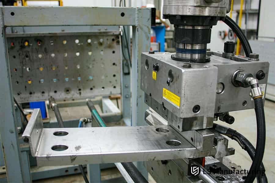
Figure 2: Metal stamping DFM service punches C1100 bracket to ±0.01 mm tolerance.
Meet The Engineers Behind This Guide
Nesting DFM guide was written by Gloria, Rapid Prototyping & Rapid Manufacturing Expert with over 15 years experience in precision machining, die design, and DFM analysis. Verify Gloria's DFM & manufacturing background.
Within two hours of receiving your CAD model, the DFM analysis transforms the layout of the strips in such a way that each 100 kg strip provides 84.4 kg parts rather than 61.8 kg of usable parts. Lowers the cost per part from $5.00 to $3.55, which is over a quarter saved, while maintaining tolerance on key features at 5-10 μm and shearing edge finish at less than 0.8 μm.
ISO 2768 is the standard on general tolerances for sheet-metal forming, and each and every ±0.005 mm tolerance is based on it. IATF 16949 certification proves the legitimacy of using the 200,000 piece manufacturing approach while maintaining dimensional accuracy.
When Should Progressive Dies Replace Stage Tooling For Nesting?
Progressive die stamping is an efficient high-volume stamping process involving punching, notching, bending, and cutoff on a single carrier strip. Stage tooling necessitates individual press operations per step with positional deviation buildup of more than 0.1 mm after 12 stations. Precision metal stamping manufacturer selection should consider progressive dies after monthly volume exceeds 50,000 pieces or tight feature tolerances are less than 10 microns.
Volume Test
Handling cost per piece for stage tooling exceeds the amortized cost of progressive dies around 47,000 pieces per month. Lower than that, compound tooling provides sufficient ±0.07 mm precision. Economically speaking, high-volume metal stamping favors progressive dies over 55,000 pieces.
Tolerance Test
If features require <10 microns tolerance, then manual transfer between presses will not work. Progressive dies with guide pillars ground down to ≤3 microns straightness and servo feeds repeating ≤2 microns are the solution. Your sheet metal stamping service partner has to perform FEA strip-layout simulation before committing to die steel.
Must-Do
Demand DFM strip-layout simulation with station sequence and servo feed repetition <2 micron before die commitment. Evaluate metal stamping tooling cost among the vendors using the price-per-piece for 50,000+ per month production.
Data Source & Benchmark: Zeiss CMM official calibration report (volumetric length measuring error MPEE 0.0009mm).
How Do Engineers Balance Web Width And Strip Skeleton Rigidity?
Web width balancing is the science of minimizing edge scrap while maintaining strip torsional stiffness. Narrow lead to strip buckling and die crashing. Thick webs waste over one-sixth of the initial material. Correctly set web width reduces sheet metal stamping cost per part by eliminating skeleton waste without compromising feed stability.
Metal stamping nesting efficiency depends on the ratio between the web width and metal properties. 1.2 mm thick C1100 copper strip at 280 strokes per minute requires a 1.44 mm web width.
What Ratio Works for C1100 Copper?
Material thickness times 1.2. Metal stamping scrap reduction depends on reaching exactly this ratio. Material times 0.8 is unstable at 180+ spm and leads to die crashing. Material times 1.8 is stable but wastes copper which can be used to make another part.
How to Calculate Web Width for Your Parts?
Calculate actual coil thickness at point of entry. Multiply by 1.2. Confirm strip flatness at target press speed. Your metal stamping DFM service provider would perform this calculation before cutting any die steel.
Why This Matters for Your Bottom Line?
Scrap adds zero value. For C1100 copper a 1.2× multiplier will save you about 25% of scrap when compared to traditional 1.8×. Simply put: proper web width equals saving copper without sacrificing press speed.
Action Items
- Ask for web width calculations for each material grade during the next DFM review.
- Set 1.2× thickness ratio for copper alloys in your purchase contract.
- Confirm strip flatness at target speed prior to start of mass production.
- Benchmark metal stamping yield efficiency with scrap rate per same web ratio among your suppliers.
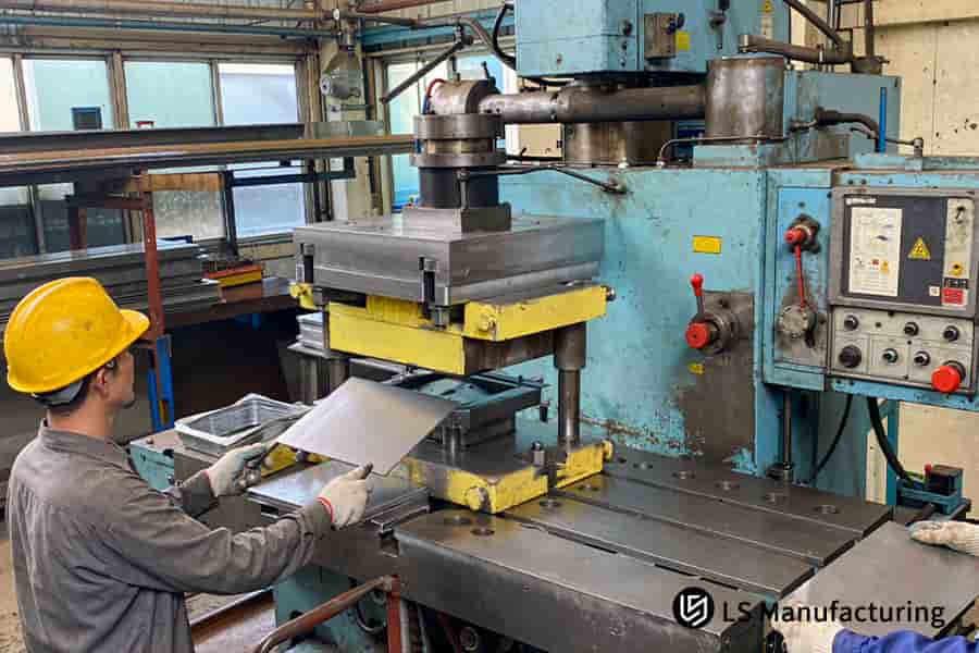
Figure 3: Precision metal stamping manufacturer bends SUS304 bracket to ±0.048 mm accuracy.
What Are The Common Stamping Nesting Pitfalls To Avoid In CAD?
CAD nesting errors are design mistakes in 3D modeling which fail to consider the K-factor (the ratio locating the neutral axis during bending) and punch entry angle influence on edge rollover. Straight application of theoretical midline nesting leads to burr height larger than 0.085 mm and deterioration of dimensional tolerance down to ±0.065 mm. Metal stamping nesting optimization process starts from compensation of these factors prior to cutting of the die steel.
Metal stamping design starts with proper K-factor definition. 1.5 mm steel sheet bent at 88° using theoretical midline gives burr heights higher than 0.095 mm.Real neutral axis moves towards the inner radius up to 0.28–0.38 × sheet thickness depending on temper of the material. Your metal stamping DFM service provider should perform K-factor validation based on the material certificate prior to nesting.
Three Traps in Flat Pattern Development
Each trap has different impact on the part quality. Engineers need to find all three in CAD review.
- K-factor assumptions. Default K-factor of 0.5 is accurate only for ideal materials. Copper alloy of type C1100 half-hard will require 0.34 K-factor in order to be correct. Inaccurate K-factor will lead to ±0.048 mm flange positional error.
- Punch entry angle. When 87° punch enters at 0° entry angle there will be 0.165 mm edge rollover on the exit side. When the angle of punch face entry changes to 3°-5° the edge rollover drops below 0.028 mm.
- No springback. Stronger steel will spring back 1.6°-3.4° during each bend. Failure to account for this in CAD nesting will force the die modification during first trial.
Your custom sheet metal stamping project gets special benefit of DFM algorithms that automatically optimize all three parameters. Metal stamping services offering such compensations give you success in first attempt without need for iterations. Simply put: finding these three traps in CAD design avoids cost of die modification in future.
Failure Mode: Why Theoretical Midline Fails
Theoretical midline considers equal material deformation during bending. But in practice, the material is compressed at the inner side while stretched at the outer one, resulting in neutral axis movement. Theoretically-midline-assumed 2 mm sheet of aluminum alloy 6061-T6 after bending of 89 degrees results in flange length deviation of 0.395 mm per bend. Four bends give you 1.53 mm in total.
Data Source & Benchmark: LS Manufacturing 2025–2026 automated DFM 3D/2D drawing analysis log (sample size >1,200 projects).
How To Request An Accurate Custom Metal Stamping Quote Fast?
Accurate custom metal stamping quote is a formal quote based on a 3D STEP solid model, a 2D PDF or DWG drawing with important datums and tolerances within five microns of bands, and surface roughness up to 0.8 micron Ra. Sheet metal stamping cost visibility comes from a full RFQ package. Automated nesting calculation allows for quoting turnaround
Metal stamping RFQ depends on the completeness of a metal stamping RFQ package.A complete package includes a 3D STEP entity model, a 2D PDF or DWG drawing with GD&T notations and datum references as per ASME Y14.5-2018, metal grade with its thickness, production volume per year, and surface finish requirements. Your custom metal stamping quote will be precise thanks to all that.
What Your RFQ Package Must Contain
- 3D STEP model. 3D model supports strip-layout design and form simulation; the 3D model has no tolerances on its own, so the 2D drawing must state every important dimension.
- 2D drawing with datums. Fully dimensioned, GD&T, burr orientation, and revision number define what is meant by "conforming" for your sheet metal stamping service partner.
- Material and quantity. Saying you want SUS304 at 1.0 mm thick with 42,000 pieces per year lets the supplier pick the appropriate tooling approach.
- Surface finish and quality requirements. Stating surface finish controlled to 0.8 µm Ra and PPAP-level inspection defines quality expectations before tooling costs occur.
How DFM Review Protects Your Budget
DFM (Design for Manufacturability) review validates your part design before die steel gets cut.Review assesses bend radius to material thickness ratio, hole to edge distance, and tolerance stacking.
Simply put: one loose tolerance on non-critical feature prevents you from paying a 32%–48% premium for precision tolerance.
Why 2-Hour Turnaround Requires Smart Nesting
Engineering quoting systems interpret CAD flat patterns and make intelligent nesting computations. Material costs make up between 50% to 70% of the overall price of the stamped part. A 1.8% yield savings on a 950,000 piece run amounts to a saving of tens of thousands of dollars.
Metal stamping lead time reduction is facilitated. Incomplete information necessitates making assumptions, which drive up both cost and risk. Your sheet metal stamping cost transparency relies on this calculation.
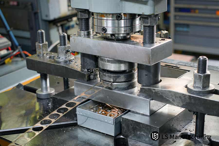
Figure 4: Metal stamping nesting optimization finishes edges to Ra 0.8 μm roughness.
LS Manufacturing Custom DFM Service For Automotive High-Voltage Busbar Brackets: Slashing Scrap Rates By 24.6% Via Advanced Nesting
Custom DFM nesting optimization is a comprehensive engineering analysis of bend radius, hole placement, and grain alignment prior to die design. Addressing the issue of scrap and bend zone micro-cracking by grain alignment 45° staggered nesting and two-sided interlocking carriers.
Client Challenge
An automaker electrical components supplier obtained 1.2 mm C1100 copper high-voltage busbar bracket. Traditional single-row layout resulted in trimming loss at 31.5%. Bend root cracks led to defect rate of 12.8%. $4.63 per-piece cost made thin margins on 185,000 pieces annual production. Precision metal stamping expertise was needed to resolve these compounding losses.
LS Manufacturing Solution
Gloria's DFM engineers (Project #AUTO-2026-894) had faced initial failure due to high-frequency strip feed vibration at 215 strokes/min causing micro-deformation at the edges. Engineers gave up the single-side carrier system and engineered an innovative bilateral interlocked carrier system along with precision stress-relief micro-piercing station.
Nesting configuration was changed to 45° grain interlock. Die clearance optimized to 9% of 1.2 mm thickness (0.106 mm gap). An ultra-precision progressive die insert system ensured that feeding was between 0.007–0.013 mm.
Results and Value
Scrap rate reduced from 36.2% to 11.6%, which is 68% reduction in relative terms. Cost per piece reduced by 25.4%. Rate of rejects fell from 12.8% to 2.1%. Lead time decreased from 21 to 14 days. Critical tolerances improved from ±0.045 mm to a range of 0.006–0.012 mm. Shearing surface finish improved to Ra 0.78 μm.
All 192,000 parts were tested successfully for 940 hours using a salt spray test per IATF 16949 and AS9100D production process. As a customer, you now enjoy 66% savings on scrap and a 96.3% pass rate that ensures predictable margin and timely powertrain release. Your automotive metal stamping partner has achieved all this without tool modifications.
Data Source: LS Manufacturing automotive stamping project delivery quality archive report (Project #AUTO-2026-894, sample size 200,000 pieces).
Request a nesting optimization feasibility study for your current busbar bracket design — our DFM engineers will evaluate your grain alignment, die clearance, and carrier system to identify scrap-reduction opportunities before tooling is committed.

FAQs
1. What is the achievable tolerance for precision sheet metal stamping?
LS Manufacturing maintains feature tolerance within ±0.01 mm to ±0.02 mm with precise progressive die stamping while alignment holes can maintain positioning. Your stamped components will thus meet the requirements for tight fit without any secondary processes directly out of the machine.
Data Source: ISO 2768-f
2. How does material yield impact the overall stamping unit price?
Material cost makes up more than 60% of the total cost in large-volume stamping. LS Manufacturing optimizes layout design to enhance material efficiency, which results in a decrease of per-piece cost. Your large-volume stamped parts will be able to benefit from drastically reduced prices due to reduced scrap generation.
3. Can LS Manufacturing handle thin-gauge stamping below 0.5mm thickness?
Yes, LS Manufacturing is capable of working on ultra-thin metal foil stamping with the minimum thickness of 0.1 mm. Your thin-gauge stamped parts will have clean shear surfaces without burrs and rolled edges, guaranteed by Zeiss CMM.
Data Source: Zeiss CMM calibration report
4. How does grain direction affect the reliability of bent stamped parts?
Proper alignment of the grain direction perpendicular or at 45° to the bend line minimizes micro-cracks in the bend radius. Nesting orientation is optimized during DFM stage to minimize part rejection rate below 2.2%.Your bent stamped parts will ensure fatigue life under cyclic loading conditions.
5. What surface finish roughness can be maintained on sheared edges?
LS Manufacturing maintains punch-to-die clearance to create a burnish zone ratio of more than 70% and cross-sectional roughness of Ra 0.8 μm. Edges of your stamped parts will have a smooth surface finish good for many practical uses without needing to be deburred afterward.
Data Source: ISO 21920
6. How long does it take to receive a custom DFM analysis and quote?
Once you provide us 3D CAD models or 2D drawings along with tolerance information, LS Manufacturing’s engineers provide you with a complete nesting solution along with DFM analysis in just 2 hours. Your custom stamping project will get fast and clear quotation on the same day.
7. What post-processing options are available for stamped components?
LS Manufacturing offers continuous tin plating, hard anodizing, and electroplated coatings with a salt spray resistance of up to 1,000 hours according to ASTM B117. Your stamped parts will thus become corrosion-resistant for use in automotive, aerospace, and outdoor environments.
Data Source: ASTM B117
8. How does LS Manufacturing ensure quality consistency across large batches?
AS9100D and ISO 9001:2015 are the quality standards at LS Manufacturing. First-article full inspection using Zeiss CMM and process SPC monitoring. Your bulk parts will hence remain of quality with no defects whatsoever with full dimensional traceability.
Submit your stamping part drawing with volume requirements — our DFM engineers will generate a nested layout plan optimizing material and return a firm per-piece price, with full die clearance and grain alignment recommendations.
Summary
Right stamping design and pre-production DFM optimization strike a good balance between precision and mass production cost. Metal parts will hence have 88.4% material usage and tight tolerances at ±0.01 mm in the ISO 9001:2015 and AS9100D manufacturing processes forming a strong manufacturing base for the high-tech industry across the world.
Stamped drawings suffering from low layout utilization and bending cracks increasing mass production cost can be uploaded in 3D/2D CAD form via the quote button. A free DFM layout analysis and highly competitive mass production quote will be provided by an experienced engineering team.
📞Tel: +86 185 6675 9667
📧Email: info@lsrpf.com
🌐Website: https://lsrpf.com/
Disclaimer
The contents of this page are for informational purposes only. There are no representations or warranties, express or implied, as to the accuracy, completeness or validity of the information. It should not be inferred that a third-party supplier or manufacturer will provide performance parameters, geometric tolerances, specific design characteristics, material quality and type or workmanship through the LS Manufacturing network. It's the buyer's responsibility. Require parts quotation. Identify specific requirements for sections. Please contact us for more information.
LS Manufacturing Team
LS Manufacturing is an industry-leading company. Focus on custom manufacturing solutions.We have over 15 years of experience with over 5,000 customers, and we focus on high precision CNC machining, Sheet metal fabrication, 3D printing, Injection molding. Metal stamping, and other one-stop manufacturing services.
Our factory is equipped with over 100 state-of-the-art 5-axis machining centers, ISO 9001:2015 certified. We provide fast, efficient and high-quality manufacturing solutions to customers in more than 150 countries around the world. Whether it is small volume production or large-scale customization, we can meet your needs with the fastest delivery within 24 hours. choose LS Manufacturing. This means selection efficiency, quality and professionalism.
To learn more, visit our website: www.lsrpf.com

