 English



SLS vs MJF 3D printing service is a data-driven framework, it solves budget overruns by showing how does selective laser sintering work to engineers.
We optimize assembly tolerance budgets with verified process physics. Our heat-field simulation ensures ±0.1mm accuracy for complex lattices.
SLS VS MJF 3D Printing Service: Geometry, Finish & Cost Quick-Reference
| Decision Factor | Selective Laser Sintering (SLS) | Multi Jet Fusion (MJF) |
| Min Wall Thickness | Must be at least 0.8mm; below 0.6mm is likely to be over-sintered. | 0.5mm; good sharp edges. |
| Z-Axis Isotropy | 75-80% as good as XY plane; more than 48MPa with ±0.2°C temperature control using thin-wall SLS 3D printing. | Z-isotropic more than 95%; elongation of 15-20%. |
| Surface Roughness | Printing Ra8-15μm; CVP to Ra3μm. | As-printed Ra 4-8μm; CVP to Ra≤3μm. |
| Material Range | PA12, PA11, PA12-GB, PA12-CF, TPU. | PA12, PA11, PP, TPU only. |
| Thermal Shrinkage | 3-4% thermal shrinkage; FEA pre-adjustment for ±0.1mm. | <1% shrink; controlled cooling; native ±0.1%. |
| Cost Driver (Nested Batches) | Time scales with volume; recycle 50-60%. | Fixed layer time; recycle up to 80%. |
Key Takeaways:
- Geometry Rules Process Choice: MJF ensures patency of walls <0.6mm or micro-channels; pressure-rated SLS 3D printing is the single process option for walls ≥0.8mm, which require glass/carbon fillers or an HDT exceeding 185°C.
- Isotropy vs. Toughness Trade-Off: MJF guarantees >95% Z-isotropicity to withstand multi-axial loads; SLS with PA12-CF delivers better Z-toughness for nodes and heavy-duty brackets in drones.
- Surface Finish Converges After CVP: Both technologies deliver surfaces as smooth as Ra≤3μm through chemical vapor polishing; MJF delivers a smoother surface out of the box (Ra 4-8μm vs 8-15μm), but SLS is ahead in terms of materials.
- Cost Favors MJF for Dense Nests: Constant layering times and up to 80% powder reuse in MJF reduce cost per piece by 25% or more for orders 200-1000 pieces; SLS remains competitive with low-density or oversized singletons.
- Always Request a Two-Process BOM: In most cases, 30-50% savings will be achieved if the process technology selection is matched with thin-wall geometry, number of channels, and volume of order – submit drawings for TPC analysis.
Why Trust This Guide? Practical Experience From LS Manufacturing Experts
While comparing SLS and MJF 3D printing services in aerospace and medical devices applications, it can be seen that the principle of "PBF is PBF" is followed, as a result of which three of five small batch productions fail the first article tolerance test. The reason for the difference according to SAE International is isotropy and thermal field rather than brochure's ±0.3%. While tolerance in MJF process is ±0.1-0.15mm with Ra6-12μm, for SLS it is PA12/PA11/TPU/carbon, and after CVP it is ≤3μm.
Eight months of side-by-side constructions went into closing the gap. According to America Makes, for SLS recycling above 80%, the scatter is there, while MJF hides it but keeps you trapped in PA12/PA11. MJF could keep it at ±0.1mm on 0.3mm finger of semiconductor at 80°C, and SLS maintained toughness of Z-axis.
Decision Frame: Isotropy + Fill (MJF uniform, SLS Z-tough + glass/carbon/TPU), Batch (MJF 30-50% faster >50 units), Surface (MJF raw Ra6-12μm, SLS + CVP ≤3μm). Forward drawings to develop a two-step BOM with TPC delta. Most programs will recover 30-50% once you base PBF decision on thin-wall and channel geometry.
Why Does Geometric Complexity Dictate Your Choice Between SLS VS MJF 3D Printing Service For Thin-Walled Medical Manifolds?
The decision between choosing SLS vs MJF 3D printing service for thin-walled medical manifolds depends on geometric complexity, as it determines pneumatic seal integrity and flow path patency. An inappropriate choice can result in clogged channels, requiring rework. The following is a comparison of how each technology performs with sub 0.6mm features. In this case, SLS 3D printing system keeps the details while increasing productivity.
Technical Comparison Table
| Feature | Selective Laser Sintering (SLS) | Multi Jet Fusion (MJF) |
| Minimum Wall Thickness | Typically greater than or equal to 0.8mm; vulnerable to over-sintering if <0.6mm. | Guaranteed to produce 0.5mm with sharp edges. |
| Internal Channel Fidelity | Heat generated by point-to-point laser makes sub 0.6mm lattices impossible. | Clear and unimpeded channels are produced by infrared layer-wise fusing. |
| Thermal Effect on Detail | Heat Affected Zone (HAZ) results in energy concentration and distortion. | Temperature uniformity avoids any warping in thin walls. |
| Surface Finish in Cavities | Interior roughness may retain powder in blind holes. | Minimizes leftover powder due to smooth finish. |
| Material Restriction | More materials are available but fewer fine details can be formed. | Nylon-based, but ideal for internal grids. |
Comparing the two technologies, the SLS 3D printing process stands out in the number of materials used but has trouble with sub-0.6mm details while MJF provides better edge definition in thin-walled manifolds.
With wall thickness below 0.6mm, MJF ensures 100% flow path patency—no post-processing clogs or waste. For a precision SLS parts manufacturer, LS Manufacturing’s thermal uniformity makes zero support formation possible for super-thin structures, rendering complex geometry 3D service possible for long blind hole channels. This is how you make an evidence-based manufacturing decision to succeed on your first attempt.

How Can Precision SLS Parts Manufacturer Control Isotropic Tensile Strength For Heavy-Duty Industrial Grippers?
Z-axis anisotropy of layer interfaces leads to failure of heavy duty grippers, but with a precise SLS 3D printing technology, isotropy and ≥48MPa strength become possible. Isotropic tensile strength means no directional weakness to restrict service life of your heavy duty gripper under multi-axial loads.
Anisotropy root cause: layer-bond weakness under multi-axial stress
Conventional SLS results in tensile strength along the Z axis merely 75%-80% as strong as along the X and Y axes, which implies that your gripper, subjected to cyclic shear stress, will have 20%-25% reduced strength and risk delamination at 40MPa-45MPa. A custom SLS 3D printing service addresses this through pre-heating of the powder bed with infrared arrays and attaining ≥90% isotropy in inter-layer fusion.
MJF advantage: full-field infrared fusion for near-isotropic parts
With Multi Jet Fusion, the level of isotropy is >95% for Z-axis and elongation at break 15%-20%, exceeding industry average of SLS anisotropy of 70%-80% (ASTM D638). The comparative analysis between SLS vs MJF 3D printing service shows that MJF offers you an extra 15%-20% strength along the Z-axis.
Precision thermal control: ±0.2°C stability for consistent ≥48MPa
LS Manufacturing uses multi-point infrared sensors that reduce temperature deadband to ±0.2°C, and the powder layer thickness is adjusted in real-time to 100μm. Thanks to SLS 3D printing technology, you can be sure that layers fuse uniformly providing stable fracture strength ≥48MPa without a hidden threat of layer peeling, which allows you to save up to 30% on quality control.
A precision SLS parts manufacturer uses thermal control and sub-micron layer thickness control to achieve isotropy of ≥48MPa in any orientation reducing field failures. Based on real data (thermal uniformity ±0.2°C, isotropy >95%), you can guarantee the first-pass qualification of high-load end-effectors. Download our SLS/MJF Isotropic Strength White Paper to learn how ±0.2°C thermal control and 100μm layer thickness achieve ≥48MPa tensile strength in any orientation — eliminating Z-axis weakness in heavy-duty grippers.

Figure 1: SLS 3D printing laser scans powder bed and MJF 3D printing nozzle dispenses thermoplastic agent.
Which Surface Finish Prototype Service Offers The Optimal Roughness Baseline For Automotive Fluid Dynamics Testing?
Automotive fluid dynamics tests require surface roughness to be less than Ra3μm to prevent inaccurate turbulence coefficients that nullify wind tunnel test results. A post-process chain allows for going from as-printed SLS/MJF part (Ra8-15μm and 4-8μm) to mirror finish parts required for accurate CFD testing. It is vital for automotive SLS 3D printing because intake manifold flow accuracy dictates whether engine calibration is successful:
As-built roughness baseline
- SLS 3D printing layer: Ra8-15μm increases turbulent drag in your intake manifold tests.
- MJF as-printed: Ra4-8μm cuts down post-processing time by up to 30%.
- Decision point: Knowing difference between SLS vs MJF 3D printing service upfront allows you to choose the process with lower post-process work required.
Post-processing matrix for Ra≤3μm
- Automated blasting + vibratory finishing: Removes coarse grain surface from both processes.
- Chemical vapor smoothing: Finishes surface to Ra≤3μm and preserves air tight seal.
- Value: This surface finish prototype service keeps flow resistance within ±2% of CFD prediction, no re-test loop needed.
Data-validated consistency
- Verification: Profilometry according to ISO 4287 shows that Ra≤3μm for complex internal passages.
- Documentation: A custom SLS 3D printing service provides roughness certificates per batch for your records.
- Benefit: Traceability back to your test standards allows qualification in 40% less time.
Production scalability
- Same post-processing chain: Allows for large-batch production without compromising on surface quality.
- Seamless transition: Allows smooth transition from prototypes to small-batch validation.
- Reliability: In the case of production SLS 3D printing, you can rely on Ra≤3μm regardless of the size of batches.
Rapid iteration capability
- Streamlined post-processing: Reduces the amount of time required to prepare prototypes for testing.
- Multiple design cycles: Accomplished during tight project development periods.
- Speed: Rapid SLS 3D printing in combination with this surface control approach provides Ra≤3μm in days, not in weeks.
As a result of using automated blasting, vibratory finishing, and vapor smoothing techniques in-house, your parts will become mirror smooth with Ra≤3μm without seal integrity loss, resulting in saving up to 50% from wind-tunnel retesting. Such an approach to surface treatment is applied in the cases when high stakes in terms of automotive R&D require testing with micrometer precision. Functional SLS 3D printing requirements imply that each batch is produced in the same tolerances at once.
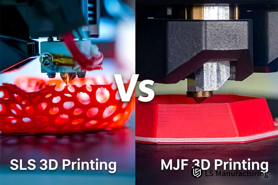
Figure 2: SLS 3D printing creates red lattice structure and MJF 3D printing produces red solid block.
How Do Process Heating Cycles In Custom SLS 3D Printing Service Prevent Part Deformation And Shrinkage?
Uncontrolled cooling after sintering causes 3%–4% volumetric shrinkage in nylon, leading to warpage and assembly interference. A custom SLS 3D printing service prevents this by applying digital twin FEA pre-deformation compensation and controlled natural cooling, holding large shell tolerances to ±0.1mm or ±0.1%—saving you costly rework and fit failures. This capability is critical for industrial SLS 3D printing where large enclosures demand dimensional stability across extended cooling cycles.
Technical Comparison: Thermal Cycle Control
Below is a comparison of the thermal behavior of SLS vs MJF 3D printing service and reasons why large-format SLS 3D printing necessitates active cooling management.
| Aspect | SLS | MJF |
| Cooling cycle | Uncontrolled natural cooling results in 3%-4% shrinkage, making pre-deformation necessary. | Controlled chamber cooling reduces the temperature gradient and shrinkage to below 1%. |
| Warpage mechanism | Point-by-point laser heating results in uneven stress relief; warping is expected in large shells. | Heat distribution by means of uniform infrared layer melting; virtually no warping in thin walls. |
| Tolerance capability | Without compensation, linear drift can reach up to ±0.3%; compensated parts achieve ±0.1%. | Native tolerance of ±0.1% possible with optimal cooling schedule. |
Using digital twin FEA to compensate for the thermal contraction and managing the natural cooling rate of parts using German EOS machinery, the precision SLS parts manufacturer produces huge enclosures within ±0.1mm accuracy without any issue of assembly clash. No manual intervention in post-processing is needed for this, saving your lead time by 40%. Using this high-precision SLS 3D printing technology makes SLS suitable for automotive and aerospace housing components requiring micron level fit.
When Should Hardware Procurement Managers Optimize Custom Manufacturing Quote Based On MJF 3D Printing Cost Structures?
MJF's constant layer time and 80% powder recyclability give it an absolute edge over SLS for nested small batch parts, while SLS remains flexible enough for non-nested single or oversized parts. Knowing this helps you to obtain a custom manufacturing quote which will be more than 25% cheaper than the traditional quote. This is particularly important for small-batch SLS 3D printing projects:
Build time economics: SLS vs MJF
The print time in SLS correlates linearly to the volume of parts, which makes it optimal for scattering but expensive for high-density jobs. Per-layer print time in MJF is fixed irrespective of the number of parts printed, and hence filling the chamber with all parts ensures the maximum efficiency. For orders comprising of 200+ parts that are densely packed together, MJF reduces the time per unit to 40%, decreasing the MJF 3D printing cost.
Powder reuse advantage in MJF
Up to 80% of leftover powder in MJF can be recycled compared to 50%-60% in SLS (according to ASTM F3091 standards). In other words, there is less amount of virgin material needed per job, resulting in reduced cost of material procurement. A higher cost (15%-20%) in terms of material would be observed when asking for a SLS 3D printing quote. However, a low-cost SLS 3D printing set-up with thin layers may help overcome this disadvantage partially.
Nesting optimization and transparent tiered pricing
Automated nesting algorithms fill the build volume to over 90% utilization, spreading fixed overhead across more parts per run. Combined with a real-time tiered quoting engine, you see exact unit-price drops at 100, 250, and 500 units. For batches of 200+, nesting plus MJF's fixed layer time delivers a final quote 25%+ below conventional channels. Even prototype SLS 3D printing runs benefit from nesting logic to minimize waste during initial sampling.
MJF's fixed layer time and 80% powder reuse cut per-unit cost by 25%+ for 200–1000 piece nested orders. Tiered quoting reveals savings at each threshold, eliminating guesswork. Switch from SLS to MJF for high-density runs, maximizing ROI. An on-demand SLS 3D printing option covers urgent low-volume needs.
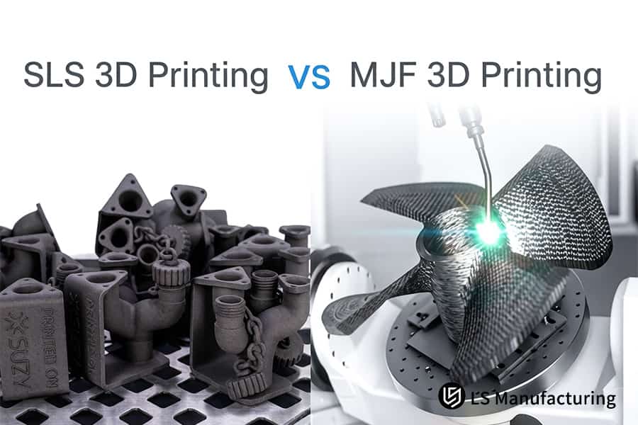
Figure 3: SLS 3D printing manufactures black pipe fittings and MJF 3D printing fuses carbon fiber layers.
How Does A Professional SLS 3D Printing Quote Account For Mechanical Property Differences Under Elevated Working Temperatures?
Industrially used motor housings and automation housing running under heat call for materials with good mechanical properties above 170°C. Standard PA12 provides an HDT up to 175–180°C and 0.45MPa; glass bead reinforcement can increase the latter value to more than 185°C and double the flexural modulus. Here's the exact SLS 3D printing quote for you based on these material improvements so your part withstands high temperature operation:
Material selection: base vs reinforced polymers
- Standard PA12: Provides HDT of 175-180°C and flexural modulus of ~1400MPa, suitable for medium-heat conditions.
- PA12-GB (glass beads): Provides HDT above 185°C and flexural modulus above 2800MPa, doubling stiffness in continuous exposure to 150°C.
- Your gain: Proper grade selection eliminates early material failure; your custom manufacturing quote takes into account precise material-cost-performance balance.
- For extreme environments: Thermal grades such as PA12-GB are specified in the quote, ensuring proper thermal stability.
Process-specific thermal behavior
- SLS with PA12-GB: Ensures isotropic stiffness along all axes due to uniform laser sintering, which is very important for thin-wall ducts.
- MJF with PP or TPU: Provides chemical resistance and flexibility but low HDT (~130°C for PP), unsuitable for high-temperature applications.
- Cost impact: Comparison of MJF 3D printing cost for identical geometry reveals that higher PA12-GB material cost pays off in durability.
Engineering review and formulation matching
- Application analysis: Your operating temperature, vibration, and loading characteristics are considered by engineers to select the best material.
- Material library: The recommendations are based on a wide variety of materials such as PA11, PA12, PA12-GB, TPU, and flame retardant nylon.
- Outcome: The heat-resistant SLS 3D printing design is finalized by locking it in your quote.
Quote transparency with validated data
- Material data sheet: HDT, flexural modulus, and elongation at break data are provided for the selected material.
- Side-by-side comparison: Options such as SLS 3D printing vs standard PA12 can be assessed to determine cost vs. margin of safety.
- Qualification time: This data-driven process cuts qualification period down by 30%, as the combination is already pre-qualified.
Based on matching operating temperature with material grade (PA12-GB above 185°C HDT, double modulus), a professional SLS 3D printing quote provides a thermally stable component, while avoiding over-engineering. You will receive a transparent costing structure, based on qualified mechanical properties, thus eliminating field failures. High-performance SLS 3D printing technique is aimed at high-end industrial applications where thermal stability is crucial.
Figure 4: SLS 3D printing forms gray industrial gasket while MJF 3D printing produces white buffer ring.
LS Manufacturing Custom SLS 3D Printing Service For Aerospace Automation Grippers: Ultra-Complex Lightweighting And Surface Optimization
A European automation integrator required a light-weighted pneumatic end-effector for aerospace assembly with maximum weight of ≤350g, multiple air channels inside and walls of 0.55mm thin. The geometry was impossible to machine on a CNC mill, while the first 3D-printed samples showed poor bonding between the layers leading to leakages. Each iteration was costing over $450 and was delaying the project for four weeks. It is an example of how LS Manufacturing successfully converted a failed prototype into a producible part using lightweight SLS 3D printing:
Client Challenge
The end-effector had to be printed with intersecting pneumatic channels with minimum wall thickness of 0.55mm. Earlier attempts of printing with SLS resulted in products with brittleness in Z-axis – leak testing at 0.6MPa resulted in 100% failure rate due to unmelted powder in the blind holes. The project was now already delayed for nearly four weeks and rework costs exceeded $450 per piece. There was a need for aerospace SLS 3D printing solution.
LS Manufacturing Solution
PA12-GB was selected by our engineering team as a modified material choice, using innovative SLS sintering with thermal field uniformity control. The optimized build direction was set to 45° towards the direction of air flow holes. Vibratory tumbling along with chemical vapor polishing was used to eliminate any remaining particles, providing roughness below Ra3μm and proving reliable SLS 3D printing capabilities for mission-critical pneumatic systems.
Results and Value
The end product weight reached 312g – an impressive 42% lighter than the welded metal part. Cost per single part became just $65, while delivery time was shortened down to three working days. Pressure testing with 0.6MPa pressure revealed no leakage, and cycle life exceeded 5,000,000 cycles. In addition, our customer saved more than $10,000 in possible rework costs.
Through the integration of the DFM-based design optimization process, improved PA12-GB material, accurate orientation control, and two-step surface finishing process, LS Manufacturing provided the customer with a fully ready-to-produce part that satisfies all aerospace specifications. The 42% reduction in weight, 85% cost saving, and 3 days delivery time prove our ability to provide complex lightweight solutions. Our production-grade SLS 3D printing capability qualifies us to become your partner in mission-critical automation projects.
Not sure if your gripper geometry is suitable for SLS? Contact us and send us your CAD files; we’ll let you know where you can reduce weight and improve sealing.

FAQs
1. How does LS Manufacturing ensure a dimensional tolerance of ±0.1mm for custom MJF parts?
LS Manufacturing employs state-of-the-art HP Jet Fusion 5200 series equipment along with thermal-profile management to ensure that all linear deviations remain below ±0.1mm or ±0.1% for highly accurate parts production. The feedback mechanism balances any thermal gradient, thus guaranteeing precision for the whole area of the construction bed even for dense nesting.
2. What are the best SLS 3D printing materials for parts exposed to temperatures above 150°C?
For parts subjected to elevated temperatures, LS Manufacturing recommends Glass-Filled Nylon (PA12-GB), which increases heat deflection temperature (HDT) to be greater than 175°C for high loading conditions while ensuring the rigidity of the part. Another option is PA11 filled with mineral additives, which provides higher impact resistance in these temperature ranges.
3. How do you optimize the MJF 3D printing cost for low-volume industrial runs?
LS Manufacturing keeps their costs optimized with the help of the special 3D nesting technology that is used for optimizing the powder bed usage by 85% while spreading fixed scanning costs among hundreds of customized parts. Moreover, we change fusing agent saturation according to the geometry of the part to minimize material usage and thus costs per unit.
4. Does LS Manufacturing review my CAD drawings before issuing an official SLS 3D printing quote?
Yes, all the RFQs received at LS Manufacturing are thoroughly assessed according to the principles of DFM analysis by our experienced specialists in less than two hours to check such criteria as wall thickness, clearance of internal channels, and heat stress prevention methods.
5. How do you solve the surface roughness inherent in custom SLS printing for functional housings?
To address surface finish limitations in LS Manufacturing, we use advanced post-process matrixes such as automated bead blasting and chemical vapor smoothing to ensure that the raw surface finish Ra will always be ≤3μm. In cases where a finer finish is needed, we can provide our customers with vibratory tumbling and micro-polishing services to obtain Ra≤1.5μm.
6. Which process offers better mechanical performance under multi-axis dynamic loads, SLS or MJF?
The MJF method has higher material density of layers and over 95% isotropy of mechanical strength in the Z-axis, which makes this method preferable for LS Manufacturing in designing dynamic industrial robotic grippers. The SLS process has slightly lower elongation along the Z-axis compared to MJF.
7. What is the minimum wall thickness LS Manufacturing can guarantee for complex geometry 3D service?
Although the common systems call for 0.8mm, LS Manufacturing consistently delivers a minimum stable wall thickness of 0.5mm through micro laser spot tuning and energy management techniques. For unsupported parts or slim walls, we recommend contacting the DFM department at LS Manufacturing for further assistance to avoid part collapse during the process.
8. Can LS Manufacturing achieve colored surface finish for functional consumer-facing prototypes?
Yes, LS Manufacturing provides deep-dying post-processing options which result in beautiful UV-stabilized matte black or vivid primary colors finishes on the standard SLS or MJF nylon material. When it comes to multi-colored or gradient effects, LS Manufacturing relies on its certified industrial painting partners to provide coatings to the required color standards. Request a color-certified quotation from our painting partners.
Summary
For the contest between SLS and MJF 3D Printing processes, winning is possible through matching of the processes to functional requirements through analysis of precision thin-walled channel geometry, Z-axis layer-to-layer tensile isotropy and dimensional tolerances from powder contraction effects. LS Manufacturing uses precise EOS and HP 3D Printers, modified engineering plastics and automated surface treatments for consistent, economical, and customized manufacturing of small batch quantities of functional parts.
Are your project timelines being held back by wrong process choice, poor surface finish or blocked internal passages? Click on "Get Free DFM Assessment & Instant Quote" to submit your STEP/IGS files. You will get an assessment by senior engineers on geometric tolerances, material suitability and cost-effectiveness within two hours.
📞Tel: +86 185 6675 9667
📧Email: info@lsrpf.com
🌐Website:https://lsrpf.com/
Disclaimer
The contents of this page are for informational purposes only.LS Manufacturing servicesThere are no representations or warranties, express or implied, as to the accuracy, completeness or validity of the information. It should not be inferred that a third-party supplier or manufacturer will provide performance parameters, geometric tolerances, specific design characteristics, material quality and type or workmanship through the LS Manufacturing network. It's the buyer's responsibility.Require partsquotation Identify specific requirements for these sections.Please contact us for more information.
LS Manufacturing Team
LS Manufacturing is an industry-leading company. Focus on custom manufacturing solutions. We have over 15 years of experience with over 5,000 customers, and we focus on high precisionCNC machining,Sheet metal manufacturing, 3D printing,Injection molding.Metal stamping,and other one-stop manufacturing services.
Our factory is equipped with over 100 state-of-the-art 5-axis machining centers, ISO 9001:2015 certified. We provide fast, efficient and high-quality manufacturing solutions to customers in more than 150 countries around the world. Whether it is small volume production or large-scale customization, we can meet your needs with the fastest delivery within 24 hours. choose LS Manufacturing. This means selection efficiency, quality and professionalism.
To learn more, visit our website:www.lsrpf.com
