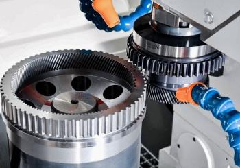
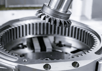
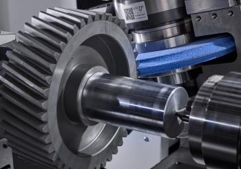
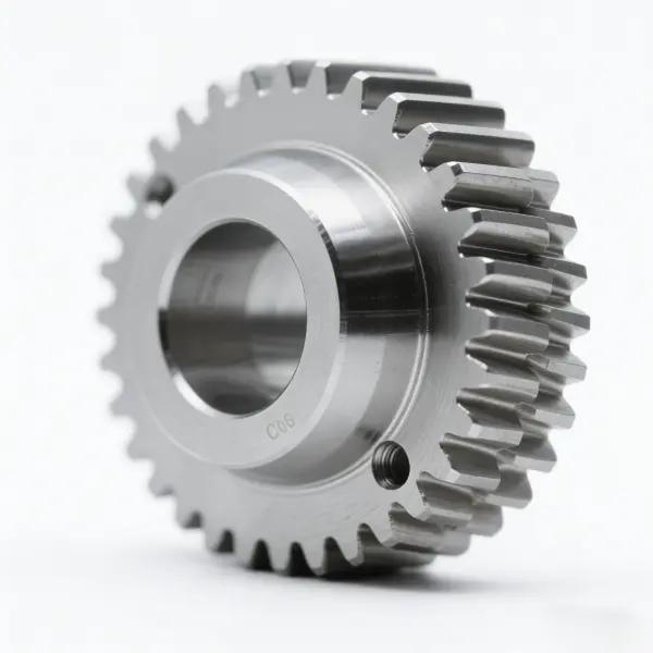
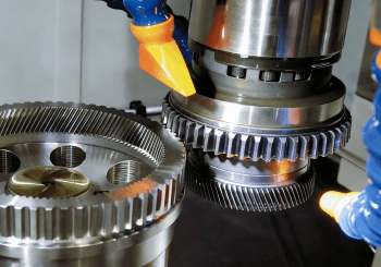
In nature, we witness remarkable symbiotic phenomena, such as the interdependence of bees and flowers and the symbiotic relationship between marine life. Similarly, in the rapidly evolving world of modern technology, the success of a high-performance gear system depends not only on the precision of the gears themselves but equally on the accuracy of their "foundation"—the precision-machined housing or mounting plate, as shown in the image. Next, we will explore the full scope of custom gear manufacturing. This encompasses not only the gears themselves—the "heart" of the movement—but also the customized structural components that precisely secure them. After all, a successful transmission system is much more than just the gears themselves.
Article Objective: This guide will show you about the process of purchasing a complete, high-reliability mechanical system, from the gear machining parts you need to the precision frame that ensures flawless operation, and break down the cost components of each step. Now, let's dive in.
Anatomy of a High-Reliability Mounting Frame
We can see the part in the picture, it is a critical gearbox housing, chassis or motor mount, not a gear, and every feature of it serves the gear it carries.
Next, we will introduce the analysis of key features: mounting bosses and bearing seats, precise positioning holes, and complex weight-reducing holes/slots, and finally the selection of materials.
Key Feature Analysis |
Reference Image Details |
Mounting Boss and Bearing Seat |
The cylindrical features in the corners are not decorative; they are precision seats for bearings or drive shafts to mount. The accuracy of their diameter and position is crucial. |
Precise Positioning Holes |
The small holes in the frame are used for fasteners. Their "true position" tolerance relative to the bearing seat determines the final alignment accuracy of the entire system. |
Complex Weight-reducing Holes/Air-Avoiding Grooves |
The organic, wavy cutouts are designed to provide clearance for large gears, motors, or other components. |
The part is likely machined from 6061-T6 aluminum alloy due to its excellent strength-to-weight ratio, thermal conductivity (to dissipate heat generated by the gears), and superior machinability. |
Critical Tolerances: How the Frame Determines the Fate of the Gear
Center distance tolerance
It refers to the maximum allowable deviation in center distance during gear design and manufacturing. This deviation can be positive or negative, meaning the center distance can be slightly larger or smaller than the theoretical value. Center distance tolerance is a critical parameter in gear transmission systems, directly impacting gear mesh quality, transmission accuracy, and service life.
An incorrect center distance can lead to noise, low efficiency, and rapid failure. When designing and manufacturing gears, it's important to select the appropriate center distance tolerance based on actual conditions to ensure proper operation of the gear transmission system.
Parallelism and perpendicularity
Parallelism and perpendicularity are both directional tolerances, controlling the degree of tilt of a feature relative to a datum. Parallelism controls parallel relationships, while perpendicularity controls perpendicular relationships.
The flatness of mounting surfaces and the parallelism between shaft holes are prerequisites for preventing system binding and ensuring even load distribution on the tooth surfaces.
In mechanical design and manufacturing, the proper application of parallelism and perpendicularity tolerances can effectively ensure product precision and functionality.
Sourcing Your Gear Machined Parts
First, we will briefly introduce you to common gear types such as spur gears, helical gears, bevel gears and their main applications. Detailed information is available in the table below.
Common Types of Gear
Types of Gear | Features | Application |
Spur Gear | The tooth shape is straight and parallel to the gear axis, with a simple structure, easy to manufacture, and high transmission efficiency (up to 98%-99%). However, the noise is loud when meshing, and the impact is more obvious because the single tooth contacts and bears the load. |
1. Low-speed, low-torque applications (such as clocks and printers). |
Helical Gear | The helical teeth form a certain angle with the axis (usually 15°-30°), which increases the contact area during meshing, ensures smooth transmission, and reduces noise. However, the helical teeth generate axial forces, requiring thrust bearing support. | 1. High-speed, high-load equipment (automotive transmissions, industrial reducers). 2. Applications requiring low noise (elevators, wind turbine gearboxes). 3. Heavy machinery (mining equipment, marine propulsion systems). |
Bevel Gear | These gears are arranged on a conical surface and are used to transmit power between intersecting shafts (usually at 90°). They are classified as either straight bevel gears or spiral bevel gears (the latter being quieter and having a higher load capacity). They are also more complex to manufacture. | 1. Changing the direction of transmission (automobile differentials, drilling rigs). 2. Right-angle transmissions where space is limited (helicopter main rotor drives, food mixers). 3. Spiral bevel gears are used in high-performance vehicles (racing cars, heavy trucks). |
Professional manufacturing process: Distinguishing between gear machining and general CNC machining
The Core Difference Between Gear Machining and General CNC Machining
Dimensions |
Gear Machining | General-purpose CNC Machining |
Process Objectives | Precise control of tooth profile, tooth profile, and meshing characteristics. | Cutting of free-form surfaces or simple geometries. |
Equipment Specificity | Requires gear-specific machine tools (hobbing, gear shaping machines). | General-purpose three-axis/ five-axis CNC machines. |
Tool Characteristics | Specialized forming tools (such as hobs and gear shaping cutters). | Standard milling/turning tools. |
Precision Requirements | DIN/AGMA Grade 5 or higher | Typically IT7-IT9 |
Key parameters | Module, pressure angle, helix angle, displacement coefficient | Dimensional tolerance, form and position tolerance |
Detailed Explanation of Gear Core Processing Technology
Hobbing: The most common and efficient method for cutting gear tooth profiles.
Shaping: Used for machining internal gears or gear features near steps.
Grinding: A high-precision finishing process performed after heat treatment to correct distortion and achieve extremely high levels of accuracy.
Materials and Heat Treatment: Gear strength and durability come from the right combination of materials (such as 40Cr and 20CrMnTi steels) and heat treatment (such as carburizing and nitriding).
Finding Online Gear Machining Services
Are you still looking for gear machining services? When you need gear machining services, please consider LS. Because we are a professional gear manufacturer, not a general machining shop.
When searching for gear machining services, it may be helpful to ask the following key questions of the supplier:
1. Do they have specialized gear inspection equipment (not just a CMM)?
2. What accuracy levels can they achieve (e.g., AGMA, ISO)?
3. Do they manage heat treatment in-house or with a certified partner?
Synergistic Effect: When Precision Housing Meets Precision Gear
Are you familiar with the "barrel effect" principle? The role of gears in industry also applies to the entire system. A high-precision (and expensive) AGMA grade 12 gear will significantly degrade performance if installed in a low-precision housing. Conversely, a perfect housing cannot eliminate the noise generated by a low-quality gear. Therefore, the interaction between gear and housing is crucial to achieving a balanced and well-matched system.
So, why don’t we consider the importance of considering the housing and gears together during the design phase when designing for assembly to ensure proper fit, clearance, and assembly sequence.
Decoding Gear Machining Price
The total cost of system processing is the sum of its parts, but the cost drivers of each part are different. Here is the Comparison of Price Drivers for Housings vs. Gears table below.
Price Drivers | Gear Housing | Gear |
Cost Factors | Primarily driven by material costs (cast iron/aluminum alloy) and general machining (e.g., CNC), the mold amortization effect is significant in mass production. | More dependent on high-precision machining (e.g., hobbing/grinding) and heat treatment (e.g., carburizing). |
Processing Time | Very high. Complex features, deep pockets, and tight positional tolerances on housings require significant machine time. | High. Cutting tooth profiles is a specialized and time-consuming process. |
Material Costs | Medium. Aluminum is relatively inexpensive, but large parts require large, expensive blocks of raw material. | High. The cost of specialty gear steel and heat treatment accounts for a significant portion of the final price. |
Tolerance | Extremely high. Positional tolerances of bearing seats are the main cost driver. Growing exponentially. | As you move up the AGMA or ISO accuracy scale, the price can increase exponentially. |
Setup Costs | High. May require complex fixtures to machine all features. Unit price decreases significantly with quantity. | High. Requires specialized tooling (hobbing). Cost is amortized over production runs. |
Summary
Go beyond isolated parts – embrace a systems approach
Combine the gears with the matching housing, and you have a balanced, matched system. We need to think beyond isolated parts and embrace a systems approach. Stop thinking of "gears" and "brackets" as separate orders and start thinking of them as building a "precision drivetrain."
When requesting a quote, provide assembly drawings or background information about how the parts work together. A good manufacturer can use this information to advise on critical tolerances and create a more reliable and cost-effective solution. Elevate your next project by taking a systematic approach to custom CNC machining, ensuring every component works in perfect harmony to deliver a superior end product.
In the face of these higher challenges, LS's CNC turning service is your indispensable ultimate "tool". It represents industrial-grade precision, unparalleled repeatability and efficient productivity, allowing your design ideas to be perfectly, consistently and efficiently realized. Choosing LS is to inject industrial-grade precision power into your extraordinary craftsmanship.
Upload your design drawings now and get an instant CNC turning quote (cnc turning price), let LS be your strong backing in pursuit of ultimate woodworking precision!
📞Tel: +86 185 6675 9667
📧Email: info@longshengmfg.com
🌐Website:https://lsrpf.com/
Disclaimer
The contents of this page are for informational purposes only.LS seriesThere are no representations or warranties, express or implied, as to the accuracy, completeness or validity of the information. It should not be inferred that a third-party supplier or manufacturer will provide performance parameters, geometric tolerances, specific design characteristics, material quality and type or workmanship through the LS network. It's the buyer's responsibilityRequire parts quotationIdentify specific requirements for these sections.Please contact us for more information.
LS Team
LS is an industry-leading companyFocus on custom manufacturing solutions. We have over 20 years of experience with over 5,000 customers, and we focus on high precisionCNC machining,Sheet metal manufacturing,3D printing,Injection molding,Metal stamping,and other one-stop manufacturing services.
Our factory is equipped with over 100 state-of-the-art 5-axis machining centers, ISO 9001:2015 certified. We provide fast, efficient and high-quality manufacturing solutions to customers in more than 150 countries around the world. Whether it is small volume production or large-scale customization, we can meet your needs with the fastest delivery within 24 hours. chooseLS technologyThis means selection efficiency, quality and professionalism.
To learn more, visit our website:www.lsrpf.com