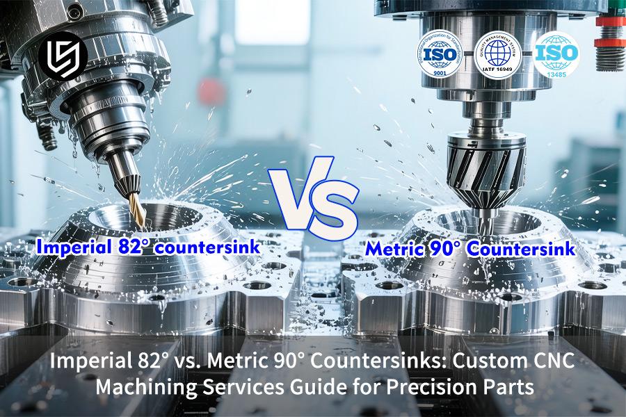
Custom CNC machining services specifically solve a critical deficiency in the precision engineering of global projects, namely, the interferences that occur in the assembly process due to the ambiguity of imperial standards for 82° and metric standards for 90° countersinks. This 8° difference, arising from a lack of clear drawings or supplier knowledge, results in screw head protrusion or unsatisfactory contact. This has critical consequences in aerospace or medical devices, where this phenomenon in fasteners will directly cause failure in critical parts of the product, namely, the fasteners, during critical stages of testing, namely, the vibration test.
This is a critical deficiency since there is a complete lack of understanding of the concepts of "contact stress distribution" and "countersink depth compensation." A 90° cutter for an 82° specification results in a devastating loss of fatigue strength, exceeding 40%, since only a point contact is achieved instead of a bearing surface. This is overcome through a process of "geometric stress simulation" and proprietary "depth models" for a 100% perfect fit. This is the first step towards reliability, which is a critical test of a supplier's expertise.

Imperial 82° vs Metric 90° Countersinks: A Machining Guide
| Key Difference | Application & Manufacturing Implication |
| Primary Use & Standard | 82° is standard in Imperial/US systems, often for use with flat-head screws. 90° is standard in Metric systems, giving a wider, more shallow fastener. |
| Head Seating & Clamping | 82° is a more acute angle, which can allow for greater axial clamping force for a given torque compared to a 90° seat. |
| Tool Availability & Programming | Accurate use of the correct standard angle is critical. Failure to do so means the fastener will not seat correctly. |
| Our Machining Protocol | We have tooling for both CNC machining standards. We verify the angle specified is correct for the fastener print or standard for perfect compatibility. |
| Result: Proper Fastener Fit | Ensures proper fit, so the fastener head is flush or below the part surface, as intended, for safety, appearance, and function. |
| Result: Optimal Joint Integrity | Ensures proper preload and clamping force for joint integrity, preventing joint failure from loosening under vibration or load. |
We take care of the critical detail of machining the proper countersink CNC machining angle for your fasteners, whether they are Imperial or Metric. This is done precisely so that you can be assured of perfect seating of fasteners, maximum clamping force, and reliability of joints, so that you do not experience any problem during assembly or when using your precision parts. This attention to detail ensures that you are able to fulfill all requirements of function and standards for your parts.
Why Trust This Guide? Practical Experience From LS Manufacturing Experts
There are many articles written about countersinks, but what sets this guide apart is that it is written from experience, having spent 15 years custom CNC machining. We have witnessed the problem of combining both Imperial standards of 82 degrees and Metric standards of 90 degrees causing assembly problems and vibration failures in critical parts for aerospace or medical applications.
We have discovered that the difference of 8° is not inconsequential, as this affects the stress distribution and compensation. Through trials, we have fine-tuned our selections of tools and CNC settings to ensure that point contact is avoided, which could lead to a loss of fatigue strength by 40%. Our methods are also in line with guidelines from the Occupational Safety and Health Administration (OSHA) and also with the trend set by Gardner Business Media, which means that our techniques for materials such as Titanium or 316 Stainless Steel are not only safe but also backed by industry.
Each of our tips has come from our successes and failures, which were costly in our early days. However, we want you to benefit from our knowledge so that you too can enjoy a perfect countersink without going through the process of trial and error. Trust that this is the same knowledge that we use to ensure that our precision parts are reliable, and we are eager to help you get things right.
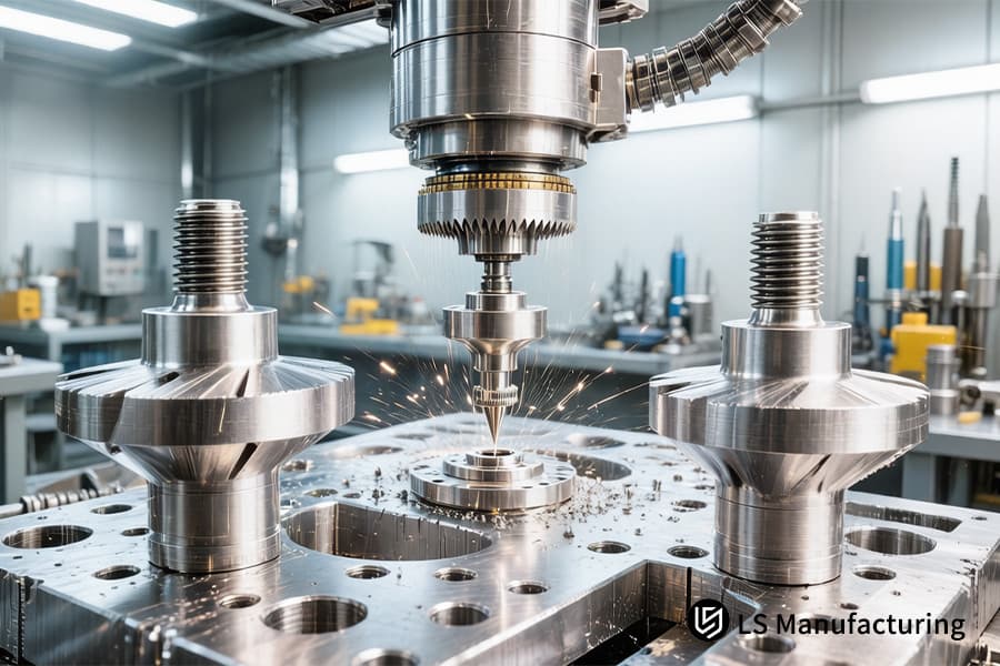
Figure 1: Machining a precise 90 degree countersink in aluminum for aerospace fastener and precision assembly components.
Why Is Understanding Metric VS Imperial Countersink Essential For Precision Machining?
In the globalized world of precision CNC machining services, the basic difference between the standard metric vs imperial countersink geometries (standard angle: 90° vs. 82°/100°) is a basic consideration often misconstrued during the design phase. This often leads to a compromise in the integrity of the joint assembly. This analysis will calculate the impact of the angle difference and the systemic verification process undertaken during the CNC machining services to guarantee the success of the assembly.
| Aspect | Imperial Standard | Metric Standard | Consequence & Data |
| Primary Included Angle | 82° (specialized aerospace - 100°) | 90° | A mismatch may cause the loss of ~60% of the desired area of the bearing surface, thereby creating a critical stress concentration point. |
| Functional Result | Non-conforming fastener seating | Correct geometric fit | A mismatch may cause the screw head to protrude or create a gap, thereby causing the screw to loosen prematurely due to vibrational forces. |
| Proactive Mitigation | Validation per AS/SAE standards for 82° | Validation per DIN/ISO standards for 90° |
By applying "dual-check logic" during CNC program verification—specifically through the cross-verification of technical specifications—we eliminate the issue of batch rework in custom precision CNC machining. |
The angle of the countersink is very critical for the longevity of the product. The critical client issue of latent drawing error is addressed through the resolution of specification conflicts, which is ensured through the machining quality protocol, thus becoming a critical advantage through the guarantee of meeting precise functional needs through the geometric verification process.

How Can Custom CNC Machining Services Ensure The Perfect Flush Fit For 82 Degree Countersink?
To achieve a perfect flush finish with an 82 degree countersink, a mathematical calculation must be made for the relationship between the fastener's head and conical seat. However, the catch here is that the design must also accommodate for the natural deflection that occurs with movement in tooling and machine operation so that screw heads are neither too high nor too low in the finished product. LS Manufacturing's proprietary answer for this situation includes computer modeling and CNC machining for precision parts:
Algorithmic Overcut Compensation
Proprietary computer software makes adjustments in real-time for the CNC milling process based on the load on the spindle and the hardness of the materials being machined, which calculates the deflection that occurs in any tooling, generally 5-15 microns, and makes adjustments for this in the actual milling process so that a perfect geometric cone can be achieved, as opposed to where the computer program dictates that the machine should move.
Multi-Axis Toolpath Optimization
This is done with a high-precision ball nose endmill cutter, or a form tool, with a 5-axis CNC machine. This approach ensures a smooth finish, with a constant level of roughness on the surface, within the range of Ra 0.8 μm, which is important for a smooth load distribution and a visually appealing finish.
Data-Driven Depth-to-Diameter Ratios
Our custom CNC machining services are backed by empirical data, which is the only factor for success in this case. This is done with an exclusive database that calculates the exact depth for a flush finish, considering the screw head diameter, tolerance, and the exact programmed depth, considering the cutting tool's corner radius as well as the topography of the machined parts, as opposed to conventional charts that provide a range of depths for a given fastener type.
This process makes what should be an elementary process, i.e., a countersink operation, a reliability-critical operation. We address this very problem of varying assembly height with our closed-loop CNC machining. This degree of technical sophistication is what sets us apart and makes our process a competitive advantage in high-value parts where a perfect flush fit is a requirement.
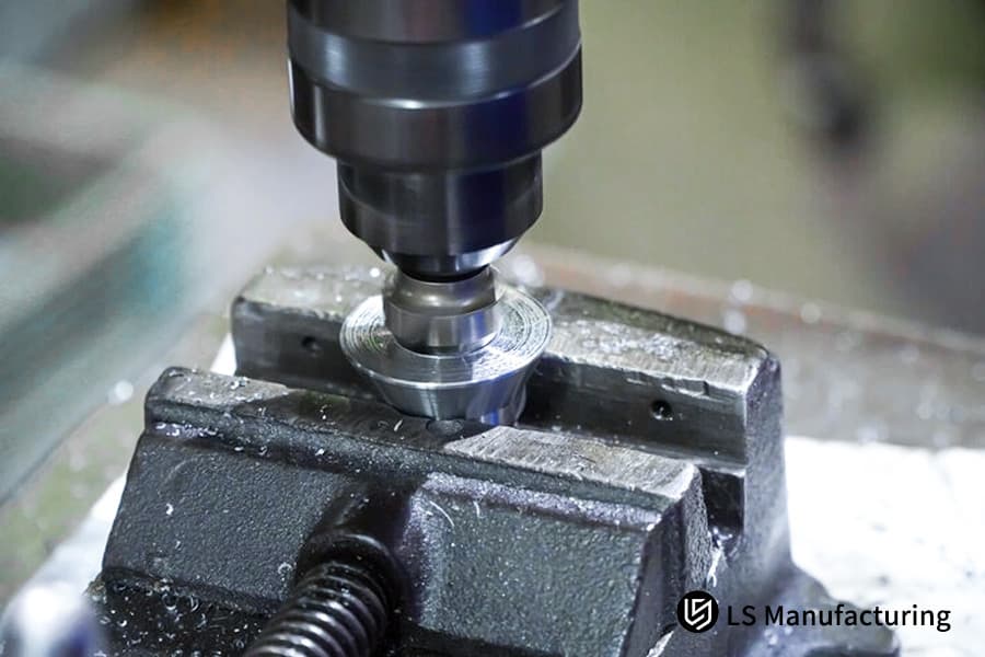
Figure 2: Machining a precise 90 degree countersink in stainless steel for aerospace fastener assembly.
What Role Does 90 Degree Countersink Plays In Global Precision CNC Machining Services?
The 90 degree countersink operation is a fundamental metric standard. However, achieving a precise operation on difficult-to-machine materials like 316L and titanium presents unique challenges in terms of tool wear, burrs, and dimensional control. Our process specifically addresses these challenges to ensure reliability in global precision assemblies:
Overcoming Material-Based Tool Wear
- Material-Specific Parameters: A proprietary database is used, which includes optimized speeds and feeds for the work hardening properties of alloys.
- Advanced Tool Selection: Only the best tools made from carbide are used, and they are specifically designed for temperature control and tool strength.
Eliminating Burrs with Controlled Toolpaths
- Staged Feed Strategy: A finishing pass is used, which includes a constant feed rate for clean severing of the parts and elimination of secondary burrs.
- Optimized Exit Paths: Tool paths are used, which take the tool away from the edge. This is a key element in burr-free countersink CNC machining.
Guaranteeing Batch Consistency with In-Process Metrology
- In-Cycle Probing: A touch probe is used, which is used for measuring the major diameters, ensuring that the tolerance is within the permissible range of ±0.01mm before unloading the parts.
- Closed-Loop Control: The information gathered from this is used for controlling the offset of the tool. This is important because we are not only precise in our operation, but we are also ensuring that we have a quality aspect of the operation, which is part of the CNC machining process.
Our solution for addressing the problem of low quality for 90 degree countersink is based on material-specific machining information, tool paths, and metrology. This is the essence of our precision CNC machining services. This is important for the absolute consistency required for high-value instrument parts and a competitive world supply chain.
Why Choose Professional Countersink CNC Machining For High Vibration Aerospace Components?
Countersink is a critical failure mode in a high-vibration environment for aerospace parts, especially for micro-crack location. The problem is, of course, that countersink needs to be performed without damage to microstructure at the edge of the hole. This is where countersink CNC machining, or "cold work strengthening," excels.
Proprietary Cold-Work Strengthening Process
Our method uses the well-controlled style of cut, which deforms the material at the edge of the countersink, as opposed to the cut method, which actually cuts the material and hence creates beneficial residual stresses that actually “armor” the hole against crack growth. This method is carried out in accordance with the CNC machining cycle and hence turns this weakness into a strength.
Optimized Parameters for Microstructural Integrity
Thermal input is one of the most critical parameters of any machining operation. In this case, the spindle speed has been optimized, especially at low speeds, and ultra-high-pressure coolant at 70 Bar has been used to evacuate the heat instantaneously, thus avoiding the creation of the thermally affected zone (TAZ), which would otherwise result in the creation of a brittle failure zone along the perimeter of the hole.
Validated Outcome Through Fatigue Testing
The efficacy of the solution is supported by empirical evidence; the internal tests for fatigue on aerospace-grade aluminum and titanium materials have shown that the custom precision CNC machining guarantees a minimum increase of 25% in the lifecycle of a fastener joint compared to a conventionally produced part.
We address the key issue of vibration failure through a CNC machining for precision parts that cold-works the material edge, avoiding thermal damage, and supported by fatigue test evidence. This technical solution, which goes beyond the geometry of the part to the metallurgy of the material, sets the standard for high-reliability aerospace components where every joint must last.
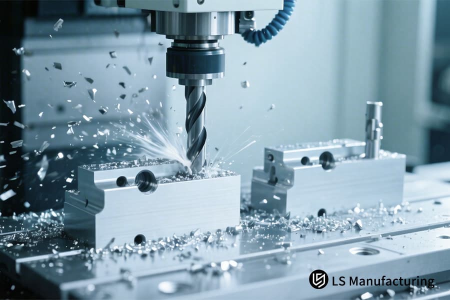
Figure 3: Machining a high-tolerance aluminum block with coolant for industrial automation or robotic components.
How Does LS Manufacturing Optimize The Cost Of CNC Machining For Precision Parts?
An efficient CNC machining cost management approach for B2B in manufacturing can be a strategic approach that focuses on improving efficiency without compromising on quality. In the case of CNC machining for precision parts, a significant percentage of the overall cost can be accounted for by non-value-added times, which include tool changes and setup times, among others. This document seeks to emphasize how our custom CNC machining services can help in cost reduction through optimization, thereby providing a framework for value-based purchasing.
| Optimization Focus Area | Key Action | Quantifiable Impact on Cost |
| Design for Manufacturing (DFM) | Coordinate countersink features to minimize tool changes. | Reduces part processing time by 15-20% for multi-feature part operations. |
| Process & Tooling Strategy | Standardize on tool families and use staged feed rates. | Increases tool life, reducing cost per part for tool consumption. |
| Production Planning | Leverage the benefits of economical batch analysis as part of the CNC machining process. | Balances the amortized cost of setups against the cost of inventory. |
| Transparent Pricing Drivers | Offer transparent cost structures for clients to understand the cost drivers related to tolerance requirements, material hardness, and volume. | Allows clients to create RFQs that meet design intent within budget constraints. |
With this methodology, we solve the major problem for clients, who are faced with issues of part costs not being managed, through providing design optimization advice, cost models, and production strategy. This is the basis of our CNC machining for precision parts. This methodology effectively controls cost as a variable for clients who need a competitive advantage for their complex and high-end CNC machining requirements, where cost and performance are both critical success factors.
LS Manufacturing — Custom Case Study: Stainless Steel Precision Panels For Avionics (Mixed 82° And 90° Countersinks)
A major multinational company in the Avionics business was experiencing major assembly issues for their world-wide control unit product, due to inconsistent standards for fasteners, both imperial and metric. This "minor" specification problem had now become a major technical problem for this company. LS Manufacturing was able to solve this problem for the company using a rigorous approach for custom processing for the precision panel:
Client Challenge
The part was an avionics interface panel made of 316L stainless steel, which required a countersink operation of 82° and 90°. The confusion of the angle by a generic shop caused an improper seating of the screw. This led to a scrap rate of 35%, where the screw sheared off at the head, causing the product validation to come to a halt. This could potentially impact the release of a critical avionics platform.
LS Manufacturing Solution
Our precision-controlled CNC machining solution utilized a simulated assembly process in 3D to define the tolerances. Dedicated coated carbide tools were designed for each angle, along with spindle speed and feed rate optimization. The innovation was the addition of an on-machine laser scanner, allowing 100% inspection of every feature’s angle and major diameter before the part was removed from the machine.
Results and Value
Once the implementation was complete, the assembly fit rate was at 100%, and the screw joints were tested at a 1.5x design load. The integrated CNC machining and inspection system also resulted in the reduction of the overall lead time by 10 days, as per the original proposed plan. The timely and error-free delivery of the parts by the company resulted in the client deciding to integrate all the panel series with LS Manufacturing, who would be their long-term partners for complex custom CNC machining projects.
This custom processing case study demonstrates that, to solve complex, multi-standard specifications, it is not just basic machining required, but simulation, specific tooling, and even metrology are necessary. It also demonstrates that there is a company, namely LS Manufacturing, that can solve the complex problem of the assembly fit rate by providing timely and error-free production of critical avionics parts.
Achieve 100% assembly integrity and accelerated delivery for mixed-standard parts with our precise countersink machining.

Which Inspection Tools Ensure The Accuracy Of Custom Precision CNC Machining Products?
Trust in custom precision CNC machining is founded upon fact rather than belief or opinion. The challenge, obviously, is the manner by which we can irrefutably validate the fact that the countersink is fully within all geometric and surface requirements for optimal assembly. To address this challenge, our proposed CNC machining solution is a multi-layered detection system—one that transforms subjective judgments into objective, concrete digital data.
Dimensional Certification via CMM
- Tool & Method: Hexagon CMM equipped with a touch trigger probe for high-density 3D scanning of the countersink.
- Output & Value: Certifies true position, major and minor diameters, depth, and circularity relative to the design.
Surface Integrity Validation via Optical Profilometry
- Tool & Method: The tool we use for the Surface Integrity Validation is a non-contact 3D surface analysis tool utilizing a white light interferometer for the surface scanning of the machined cone.
- Output & Value: This CNC machining tool measures the surface roughness (Ra/Rz) and microscopic defects on the surface, thus validating the integrity of the process for optimal load distribution.
Digital Traceability & Reporting
- Process: All the information obtained through the inspection process is automatically combined digitally.
- Deliverable: This will result in a quality inspection report, which is a vital component of our precision CNC machining services.
Our answer to the pressing need for objective quality verification is the combination of CMM, optical profilometry, and digital traceability. This multi-tiered quality verification system will give our client a certifiable and evidence-based guarantee of precision, knowing that every CNC machining component meets the high standards required.
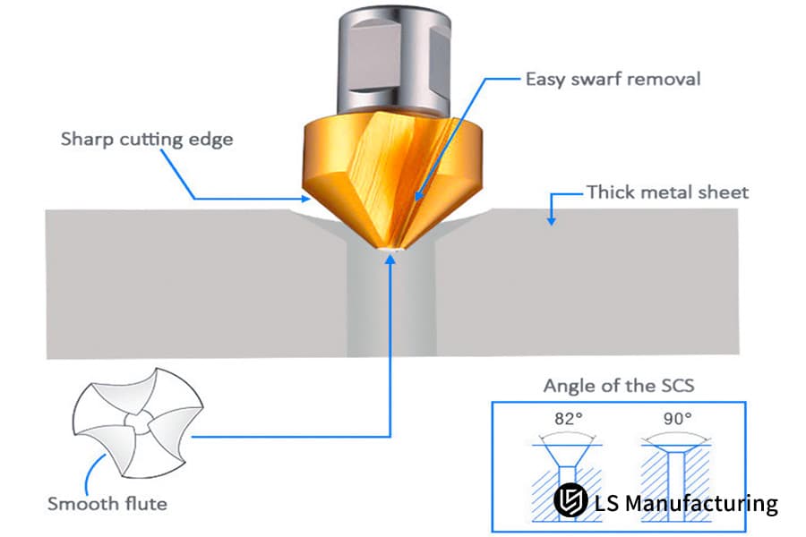
Figure 4: This diagram details a custom countersink tool with sharp edges for precision hole preparation in thick metal sheets.
Why Choose LS Manufacturing As Your Reliable Precision CNC Machining Services Provider?
In the context of the global arena of manufacturing, a competitive advantage could thus be defined as the capacity to dominate the minute details of a process to attain macroscopic reliability. The technical expertise, including the subtle distinction between metric vs imperial countersink standards, could be related to the reliability of your supply chain:
From Technical Depth to Production Certainty
We address the issue of specification ambiguity and quality inconsistency through the codification of our deep technical expertise, e.g., the tool path and depth compensation of an 82° as opposed to a 90° hole size. This expertise is encoded within proprietary process databases and CNC machining programs. This expertise translates into error-free and reliable production steps.
Transparent Operations Through Integrated Systems
We address the issue of unclear supply chain activities through a fully integrated solution. In this solution, access to the current status of your order at every step of the way, from raw material procurement through active CNC machining processes, surface treatments, and quality inspection, is transparent and secure.
A Partnership for Integrated Solution Delivery
Our value goes beyond merely making a print come to life. We are a design for manufacturability (DFM) organization, which reviews your design for areas that could potentially be problematic in the future, as with the fastener standards previously discussed. Our precision CNC machining services offer a complete solution, not merely a machined form, with the use of advanced machining techniques, in-process validation, and full traceability.
LS Manufacturing offers reliability through the systemization of our technical expertise in a transparent and controlled environment. We address complex supply chain and quality issues with certifiable consistency in our manufacturing process and complete transparency in our operations. This complete control over our business makes us the only logical choice for mission-critical CNC machining applications where failure is not an option.
FAQs
1. How does LS Manufacturing handle angle tolerances that are not explicitly specified in the drawings?
Through our DFM (Design for Manufacturability) process, we actively consult with the customer, based on the fastener standards typical for a given region (usually 82 degrees for U.S. standards or 90 degrees for metric standards).
2. Is there a difference in pricing for machining 82° versus 90° countersinks?
At LS Manufacturing, as long as the specifications are well defined, the cost of machining for these two angles is virtually identical. To get accurate pricing based on your volume and material requirements, feel free to request an instant CNC machining quote online.
3. Can LS Manufacturing produce ultra-mirror-finish countersinks (Ra 0.4μm) on stainless steel parts?
At LS Manufacturing, as long as the specifications are well defined, the cost of machining for these two angles is virtually identical; pricing levels are based on the number of holes and the machinability of the material.
4. Why does LS Manufacturing recommend adding a secondary deburring step after countersinking?
As you can see, even a small burr can cause the screw head not to fit flush against the surface of the metal. We use a robotic brushing process that ensures the burr completely disappears, even with 50x magnification.
5. Do you support custom countersinking for small-batch precision parts?
Yes. We have a prototyping workshop that is equipped to handle machining services with the same level of precision as our mass production capabilities for small batch orders between 1 to 100 pieces.
6. What solutions does LS Manufacturing offer for countersinking ultra-thin sheet metal (<1.0mm)?
We determine whether to use a combined drill/countersink operation or a back support fixture to prevent deformation of the ultra-thin sheet metal parts during the countersinking operation.
7. How does LS Manufacturing prevent tool chatter marks during countersinking?
High-rigidity shrink-fit tool holders with Variable Speed Cutting (VLC) technology are employed to effectively prevent chatter vibrations—particularly in thin-walled parts and deep holes—so that a smooth, flawless conical surface finish is ensured.
8. Can I request 100% inspection data for the countersinks from LS Manufacturing?
Absolutely. We can provide detailed inspection reports (FAI reports) for the parts according to your requirements.
Summary
Selecting an Imperial 82° vs. a Metric 90° countersink is an expression of dedication to precision in assembly. Building on our expertise in custom CNC machining, LS Manufacturing not only meets blueprint specifications with precision accuracy but also removes assembly risks for your global projects through our DFM optimization services. Every precise detail of the countersink angle is a critical factor in flawless performance, even in extreme conditions.
Do not allow a difference of mere 8 degrees become a potential failure point for your precision assemblies. Secure your project's integrity now by uploading your STEP or PDF drawings with LS Manufacturing. Our senior engineering staff will provide a detailed CNC machining quotation that will include a comprehensive "Countersink Assembly Feasibility Analysis" within a quick 4-hour turnaround.
Ensure flawless flush assembly and eliminate vibration fatigue with LS Manufacturing's expert countersink CNC machining.
📞Tel: +86 185 6675 9667
📧Email: info@lsrpf.com
🌐Website: https://lsrpf.com/
Disclaimer
The contents of this page are for informational purposes only. LS Manufacturing services There are no representations or warranties, express or implied, as to the accuracy, completeness or validity of the information. It should not be inferred that a third-party supplier or manufacturer will provide performance parameters, geometric tolerances, specific design characteristics, material quality and type or workmanship through the LS Manufacturing network. It's the buyer's responsibility. Require parts quotation Identify specific requirements for these sections.Please contact us for more information.
LS Manufacturing Team
LS Manufacturing is an industry-leading company. Focus on custom manufacturing solutions. We have over 20 years of experience with over 5,000 customers, and we focus on high precision CNC machining, Sheet metal manufacturing, 3D printing, Injection molding. Metal stamping,and other one-stop manufacturing services.
Our factory is equipped with over 100 state-of-the-art 5-axis machining centers, ISO 9001:2015 certified. We provide fast, efficient and high-quality manufacturing solutions to customers in more than 150 countries around the world. Whether it is small volume production or large-scale customization, we can meet your needs with the fastest delivery within 24 hours. choose LS Manufacturing. This means selection efficiency, quality and professionalism.
To learn more, visit our website:www.lsrpf.com.