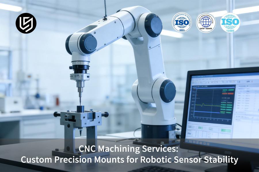
CNC machining services have traditionally been characterized by the accuracy of static dimensions, but this very approach is the cause of a widespread and expensive problem in robotics. You can easily come across sensor mounts that satisfy all geometric tests but cause "neurological tremors" in your perception system. Microscopic oscillations caused by motion or minute thermal expansion over a typical cycle of operation can ruin point clouds, blur images, and cause hand-eye calibration to go haywire, stalling automated processes without any apparent guilty party.
We address this underlying mismatch by changing the fabrication emphasis from shape replication to performance enhancement. Our dynamic stability design-manufacturing toolkit optimizes the mount as a key filter element, incorporating modal analysis, thermal-structural modeling, and the use of advanced materials such as damping alloys. The overall effect is a component with a dynamic performance passport, engineered to protect sensors from vibration levels and temperature extremes, allowing them to see clearly, aim correctly, and hit their mark.
CNC Machining for Robotic Sensor Mounts: Key Criteria
| Design Objective | Manufacturing Challenge & Solution |
| Absolute Dimensional Stability | Our CNC machining mounts must be thermally stable and vibrationally isolated; we select materials with low CTE coefficients and optimize internal structural ribbing for precise stress relief. |
| Critical Surface Flatness & Perpendicularity | Sensor interface surfaces must be highly flat (e.g., <0.01mm) to avoid measurement errors; we accomplish this with precision face milling and subsequent machining lapping. |
| Vibration Damping Integration | Passive damping mounts require elastomer mount hole positions or internal cavities; we machine critical mount pocket hole positions and tapped hole locations for optimal alignment. |
| EMI/RFI Shielding Integration | Our passive damping mounts require elastomer mount placement or internal cavities; we machine critical mount pocket and tapped hole locations for optimal alignment. |
| Lightweight, High-Stiffness Design | Our design requires it to be lightweight and stiff; we perform topological optimization studies and machine complex thin-walled lattice structures from solid aluminum or titanium. |
| Our Precision Integration Process | We machine the mount in one piece; this ensures that all critical interfaces and datums are machined in one piece on a 5-axis machine for optimal alignment. |
| Result: Measurement Fidelity | We supply mounts that provide a perfectly stable and repeatable interface, ensuring accurate and reliable sensor data without any machine noise or drift. |
| Result: System Reliability | We enhance the overall accuracy and availability of a CNC machining robotic system by eliminating any influence of calibration drift and sensor inaccuracies caused by poorly manufactured or unstable mounting interfaces. |
We are concerned with the critical issue of providing a perfectly stable mechanical interface for your sensitive robotic sensor. Our precision machining expertise enables us to design and manufacture monolithic mounts that possess superior flatness, alignment, and damping properties. This, in turn, enhances the accuracy and dependability of your robotic system by ensuring that your sensor delivers accurate and noise-free information.
Why Trust This Guide? Practical Experience From LS Manufacturing Experts
While CNC machining services provide static accuracy, your robotic sensor experiences dynamic accuracy problems because of vibrations caused by incorrect mounting. Our experience has been in the trenches, where we have solved real-world problems that have arisen because of geometrically correct brackets that create instability in the overall system, and where blurry vision and calibration problems have made things worse for us. Our battle against micro-vibrations, according to the principles described on Wikipedia, has been taken to practice.
Our engineering process for a custom precision mount takes what would otherwise be a passive component and turns it into an active stability filter. We perform complex FEA simulations for modal and thermal structural analysis, and topological optimization to optimize the material for maximum stiffness and minimum weight. Our material choice, strictly following guidelines outlined by the Metal Powder Industry Federation (MPIF), is centered on high damping materials that have the ability to absorb vibrational energy, such that the performance of the mount is assured at its very material structure.
The end result is a piece that provides sensor integrity, tested and proven in thousands of applications in the most demanding environments. We’re passing this knowledge on to you, so that you can specify with absolute assurance, what could have been a catastrophic error chain into a bulletproof element of system reliability. That, in essence, is the real difference between a machined piece and a truly performance-engineered basis of perception.
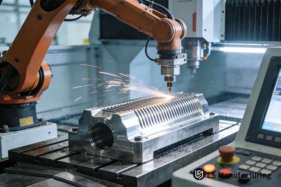
Figure 1: Active CNC machining precision metal mounts for robotic sensor stability in industrial applications.
Which Vibration Sources During Robot Motion Threaten The Stability Of The Sensor Mount?
A good robotic sensor stability mounts design beginswith understanding the enemy. The challenge is that, proactively, we must design against the specific vibration sources in robotics that lead to perception degradation, shifting our paradigm from a reactive design to a proactive design. Our solution is a CNC machining strategy:
Systematic Vibration Source Profiling
We start by identifying the operational vibration spectrum of your particular robot, considering it as the critical design input. This requires collaborative testing or the use of known vibration profiles for typical actuators and transmissions. The aim is to correlate the significant excitation bands, ranging from the low-frequency servo motion to the high-frequency bearing noise, to ensure that our design addresses the real threat environment, not hypothetical ones. This correlation directly influences the modal analysis for mounts and all design choices.
Targeted Dynamic Design via Advanced Simulation
Having established the threat spectrum, we can now apply Finite Element Analysis to perform accurate modal analysis for mounts, geometrically optimizing them to detune the structure away from the significant excitation frequencies. We can add material to the mounts using CNC machining topology optimization, maximizing stiffness and moving resonant points, such as the first bending mode, well above the significant operational bands, thereby producing a custom-designed filter even before any metal has been machined.
Material Science and Precision Fabrication
Dynamic design is made possible through material intelligence and precision execution. We select materials like high-damping aluminum alloys for their natural ability to dissipate energy, directly opposing resonant amplification. The design is then perfected through 5-axis CNC machining and multi-axis CNC milling, ensuring the dynamic performance of the manufactured part matches that of the simulation. Stress-relief heat treatment, an essential process, is then performed on the part after machining to ensure long-term stability is achieved.
Empirical Validation and Performance Lock-In
The final, most crucial step is empirical validation. Prototypes are then tested on controlled shaker tables and impact hammer modal analysis, and the resulting frequency response functions are then directly compared to our FEA simulations. This final step of validation completes the engineering cycle, ensuring the robotic sensor stability mounts will work as a complete stability subsystem. It turns a conceptual design into a provably reliable part.
The following document describes a proven CNC machining engineering process that goes beyond generic mounting solutions to offer a stability solution that can be guaranteed to satisfy certain performance criteria. Our edge in the market: our closed-loop system, from spectral diagnosis and simulation to precision CNC machining and validation. Our answer: more than just a component, but a stable base for your most important sensor-based system.

How Can The Natural Frequency And Damping Of A Bracket Be Enhanced Through Material And Structural Design?
The following document describes a comprehensive engineering process to solve the important system trade-off problem of stiffness and damping in dynamic systems. Our answer combines the best of material science, structural optimization, and damping expertise to develop systems that not only increase CNC machining natural frequency but also reject undesired resonances.
Strategic Material Selection for Targeted Performance
- Maximizing Dynamic Stiffness: Utilize high-specific-stiffness alloys such as 7075-T6 to attain maximum natural frequency with minimum weight.
- Integrating Intrinsic Damping: Utilize high damping alloys such as M2052 within custom precision mounts to attain broadband vibration damping.
- Data-Driven Choice: Apply FEA modal analysis to guide material selection for vibration damping versus pure stiffness strategies.
Advanced Structural Design via Computational Optimization
- Implementing Topology Optimization: Utilize topology optimization for stiffness to attain mass-optimized structures with high frequency lattices or ribs.
- Design Refinement: Refine the design using size/shape optimization to arrive at the final design ready for precision CNC machining.
- Performance Simulation: Simulate the design using forced harmonic response analysis to ensure there are no operation resonances.
Integration of Passive Damping Mechanisms
- Applying Constrained Layer Damping (CLD): Utilize viscoelastic damping to attain high damping at discrete resonance peaks.
- Case-Specific Tuning: Utilize modal analysis to attain optimal CLD design and properties to attain up to 15 dB damping.
- Hybrid Strategy: Integrate high-stiffness optimized substrates with localized damping treatments for optimum performance.
Precision Manufacturing and Validation
- Ensuring Design Fidelity: Implement the optimized designs in hardware in the form of high-precision CNC machining, which ensures that the predicted performance is maintained in the finished product for the mounts.
- Empirical Performance Verification: Compare simulated performance with Experimental Modal Analysis (EMA) of the prototypes, thus completing the loop and providing custom precision mounts that meet the requirements.
The authority of our expertise is best described by explaining our process and how it is a closed-loop system from FEA-based designs to physical validation. This process, which combines the very best in topology optimization for stiffness and material selection for vibration damping, and finally implementing it in CNC machining, is the definitive solution to providing custom precision mounts that meet the most demanding requirements in terms of performance.
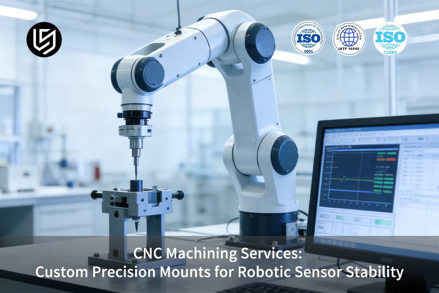
Figure 2: Fabricating high-tolerance aluminum mounts for robotic sensor stability in high-precision industrial robotics.
How Does Precision CNC Machining Achieve Microscopic Stability And Stress Control In Brackets?
Superior dynamic designs can be nullified by latent residual stresses from manufacturing, which cause micro-deformation under thermal or mechanical loads. This document details a disciplined CNC machining methodology focused on residual stress control. Our process ensures geometric integrity translates theoretical performance into guaranteed stability for the most demanding applications.
| Phase | Key Technical Strategy | Implementation & Quantifiable Target |
| Process Sequencing | Multi-stage stress-relief machining sequence. | Rough cut → Stress-relief anneal → Semi-finish → Aging → Final CNC milling (minimal stock). |
| Machining Parameters | "Low-stress" cutting parameters for thin features. | High speed, low depth-of-cut, moderate feed to prevent tensile residual stress layers. |
| Final Finishing | "Mirror"-grade finishing for critical interfaces. | Diamond tooling achieves Ra ≤ 0.2µm & flatness ≤0.01mm/100mm for CNC machining for robotic sensor mounts. |
| Integrated Service | Comprehensive precision CNC machining services. | Protocol combines multi-axis CNC machining with inspection for verified thermal/mechanical stability. |
We address the critical issue of stress-induced drift by employing a data-driven, multi-stage regimen that prioritizes residual stress control over geometry. This is an integral component of our precision CNC machining services, which provide a decisive advantage for precision parts, especially for CNC machining for robotic sensor mounts, as it ensures parts remain sub-micron stable under load.
How To Design And Fabricate A Smart Sensor Mount With Active Thermal Compensation Capabilities?
In order to effectively address the issue of precision sensor accuracy under extreme thermal conditions, it is not possible to just resist such deformation, as described in the current state of the art. The following document outlines a methodology for effectively countering thermal deformation through the application of material science, advanced fluid dynamics, and precision machining. We address the issue of alignment drift by designing structures that actively manage thermal conditions:
Heterogeneous Material Design for Passive Compensation
We address directional drift by bonding CNC machining materials with opposing Coefficients of Thermal Expansion (CTE), such as Invar and aluminum. The differential expansion calculated above provides a compensating motion. This results in near-zero net thermal drift at the sensor interface, which is the foundation of our thermal stability design for custom sensor mounting brackets.
Integrated Conformal Cooling for Active Temperature Control
For high-power sensors, we design and machine closed internal cooling channels directly into the mount. With high-precision CNC machining, we manufacture complex, closed passages. A circulating fluid actively controls the temperature of the base plate to ±1.0°C, providing a true active thermal compensation mount that isolates the sensor.
Holistic Design, Simulation, and Validation
Our approach combines predictive simulation with precise fabrication. We simulate coupled thermal-structural behavior using FEA to analyze distortion, then manufacture the design using multi-axis CNC machining. The design is validated on thermal cycling test beds, correlating simulation with experimental results to ensure sub-0.01° drift performance over broad ranges.
We do this by designing systems that not only resist thermal distortion, but also compensate for it. This is done in a closed loop of thermal stability design, precision CNC machining, and validation. Our active thermal compensation mounts address critical thermal drift issues, giving our customers a competitive edge in which robustness to environmental conditions is the defining factor of performance.

Figure 3: Machining high-tolerance aluminum brackets for precision robotic automation systems and sensor stability.
LS Manufacturing — Autonomous Driving Sector: Multi-Frequency Vibration Suppression Project For LiDAR Aluminum Alloy Brackets
In this LS Manufacturing autonomous driving case, we will present our solution to the critical issue of vibration-induced perception problems. For a client's LiDAR system placed atop their autonomous vehicle, there was a recurring issue of LiDAR point cloud jitter at specific vehicle speeds. Our engineering solution to this critical issue was to incorporate our integrated design, material science, and precision techniques to solve the following:
Client Challenge
The client's autonomous vehicle was experiencing a degradation of LiDAR point cloud resolution at highway speeds, corresponding to 40Hz and 120Hz excitations. Modal analysis of the existing die-cast aluminum bracket showed prominent resonant peaks at 95Hz and 280Hz, with inadequate damping. The essential challenge was to provide lidar bracket vibration suppression without a substantial mass penalty that would violate rooftop loading constraints, stalling the client's L4 validation schedule.
LS Manufacturing Solution
Our approach began with on-vehicle road spectrum data acquisition. We re-designed the part in 7075-T6 forged billet, employing topology optimization to develop a stiffer and lighter shape. The shape was developed through 5-axis CNC machining from a solid billet for maximum integrity. We designed in isolator pockets for shear-type metal-rubber dampers at the roof attachment point and performed multi-axis peening of the CNC machining components for improved surface damping.
Results and Value
The improved topologically optimized mount resulted in an increase in the first natural frequency to 310Hz. The transmissibility of the critical 40Hz and 120Hz frequencies of the vibration was lowered by 8dB and 15dB, respectively, eliminating point cloud jitter. This was achieved with a mere 5% increase in mass, and this swift CNC machining solution offered the much-needed reliability for sensor fusion, allowing the client's critical road testing to begin.
This particular project is a demonstration of our specialized knowledge in dealing with complex mechatronic issues at the intersection of dynamics, materials, and high-precision CNC machining. By providing a performance-verified solution for lidar bracket vibration suppression, we provided the technical knowledge required for the validation of autonomous systems.
Engineer clarity into every scan. Our CNC-machined sensor mounts suppress vibration with data-proven, application-tuned dynamic performance.

How Can The Dynamic Performance Of The Sensor Bracket Be Verified And Tested To Ensure Compliance With Design Requirements?
The accuracy of sensor information is paramount, and any source of error through mounting brackets is unacceptable. This protocol describes our validation procedure, which is intended to address the main issue of CNC machining dynamic stability. We do this by validating against resonance in structure, vibration transmission, and thermal distortion, offering conclusive proof of performance. The framework is as follows:
Empirical Modal Analysis: Correlating Physical and Simulated Behavior
- Test Method: Experimental modal test for mounts using impact hammer and accelerometers.
- Key Outputs: First three natural frequencies, damping ratios, and mode shapes.
- Validation Criteria: Comparison with FEA models, iterative improvement of the design by CNC prototype milling to reduce the margin of error in frequency to <10%.
Vibration Transmission Qualification via Swept-Sine Testing
- System Test: Fixtures placed on shaker table with input/output accelerometers.
- Core Metric: Acceleration transmissibility measurement over frequency range of operation (5-2000 Hz). Validation of vibration control mounts CNC for attenuation without unwanted resonance peaks.
- Design Proof: Validation of vibration control mounts CNC for attenuation without unwanted resonance peaks.
Thermo-Mechanical Stability Assessment
- Environmental Simulation: Thermo-mechanical cycling in controlled environment over temperature range.
- Dimensional Metrology: High-accuracy measurement of mounting interface flatness and positional accuracy at temperature extremes.
- Process Validation: Verifies stability from CNC machining material selection.
The Integrated "Dynamic Performance Passport"
- Consolidated Report: All results from the dynamic performance testing suite consolidated into a traceable certificate.
- Final Deliverable: This document will be used by our clients as objective proof of performance, well beyond the scope of traditional compliance reports.
This organized dynamic performance testing yields conclusive certification. Our empirical methodology avoids the risks of integration, thereby providing performance where it counts most. Our "Passport" is evidence of our technical prowess, yielding conclusive certification of quality and reliability. We offer a definitive CNC machining competitive edge by yielding tangible, quantifiable evidence of our dynamic inertness.
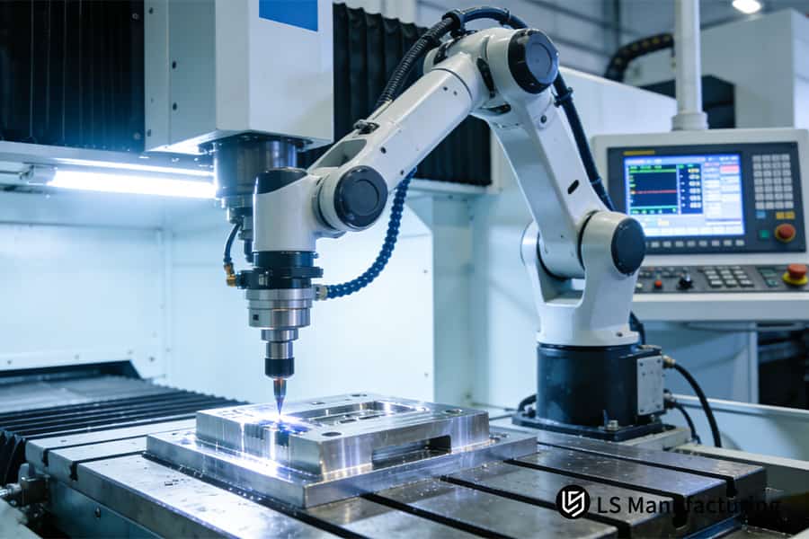
Figure 4: Producing high-tolerance stainless steel vibration control custom precision mounts for robotics sensor stability systems.
How Do You Maintain Consistency In Dynamic Performance From A Single Prototype To Mass Production?
While it is easy to attain perfect dynamic performance on a single prototype, it is much tougher to attain similar accuracy on thousands of CNC machined robotic components. Any inconsistencies in resonance or damping can have disastrous implications on the reliability of the finished product. This document yields data-driven answers to this very problem, attaining batch consistency in dynamic performance from the first piece to the ten-thousandth. Our control pillars are outlined below:
| Control Pillar | Method & Standard |
| Material Batch Stability | Require a mill certification procedure that includes ultrasonic test data and mechanical properties, such as yield strength variation < 5%, for all aluminum alloy billets. |
| Frozen & Monitored Machining Process | Develop and lock a Standard Operating Procedure (SOP) document for all CNC machining processes that define the factors of a successfully machined prototype. |
| In-Process Machining Monitoring | Require real-time monitoring of spindle vibration and machining force for high-precision CNC machining processes to detect tool wear and machining process shift. |
| Statistical Performance Validation (SPC) | Require SPC for mounts by using modal testing to establish natural frequency Cpk for a sample of each batch produced. |
| Post-Process Stabilization | Require a standardized post-CNC thermal cycle process for all parts to reduce residual stresses introduced during machining. |
| Result: Quantified Consistency | These processes allow the variation of the first-mode natural frequency to be controlled within ±3% for all production lots, as confirmed by end-of-line testing. |
This process offers a deterministic, as opposed to hopeful, answer to the problem of batch consistency for dynamic performance. This is an area of focus in high-value applications, like high-precision CNC machining components, where performance is not up for negotiation. This level of technical detail addresses the root causes of inconsistency in material, process, and verification to move consistency from hope to a deterministic, documented, and achievable result.
Why Must LS Manufacturing Be Chosen In The Cutting-Edge Field Of Pursuing Perceptual Stability?
Integrity of the sensor is of utmost significance in the advanced world of robotics and autonomous systems. The hardware mounting is not only just a hardware mounting, but it is a very important hardware mounting, and it must be able to resist multi-physics effects. Why choose LS Manufacturing? We are your single source multi-physics engineering partner, addressing the basic issue of providing stability to sensors by controlling the entire process for this very important hardware component:
A System-Oriented, Forward Design Process
We will first look at your environmental inputs, your system-level test environment's vibration spectra and thermal inputs. This is what drives our FEA-based designs, not a CAD drawing. Inherently, we have made designs that are robust to environmental inputs prior to ever cutting metal.
Precision Manufacturing as a Controlled Variable
In order to meet our design requirements, we must have a deterministic manufacturing process. This is where the use of very advanced robotics CNC machining services comes into play. This process will allow us to meet our required geometries and surface finishes. This process is closed-loop in nature, as the application of specific tooling, speeds, feeds, and a required post-CNC thermal stabilization process must be employed. This makes the process a constant, as every piece will have the same simulated results.
Empirical Validation and Performance Certification
In order to close the loop, we have our rigorous, data-driven proof. All significant builds are validated using the aforementioned methods, as outlined by our Dynamic Performance Protocol, etc. Our rigorous post-CNC validation process can be thought of as a "Performance Passport" for our parts, as it includes a datasheet for the dynamic stiffness, damping ratios, and thermal coefficients, etc. We offer guaranteed performance, not merely a part that meets print.
This is what we mean by partnership—a seamless, end-to-end process from system-aware design, through deterministic CNC manufacturing, and finally, empirical verification. It's what allows us to bring the technical expertise and accountability necessary to take what might otherwise be a passive bracket and make it a guaranteed, stable platform for your most demanding CNC machining sensing applications.
FAQs
1. What are the typical lead times and costs for customizing a high-stability sensor mount?
The whole process, including dynamic design, simulation, prototyping, and testing, can take 4 to 6 weeks. The cost of customization depends on the material, structural complexity, and performance requirements. You can get an instant quote to check the budget for your specific design. For a single prototype of a sensor mount made of 7075 aluminum alloy, using topology optimization, 5-axis machining, and modal analysis, the cost can be several thousand RMB. However, for mass production, the unit cost can be much lower.
2. How high can you typically raise the natural frequency of a sensor mount?
This is highly dependent on the size, material, and design of the mount. For a medium-sized (approx. 200 x 150 x 50 mm) aluminum alloy mount, we can optimize the design to ensure that the first-mode natural frequency is raised above 800 Hz, and even above 1 kHz, thus effectively avoiding the major excitation frequencies of most robotic systems.
3. How do you ensure the mount remains secure and free from fatigue cracks under prolonged vibration loads?
Fatigue life simulations are performed using Finite Element Analysis (FEA) to optimize the structural integrity of high-stress areas. In production, helical milling is used for all threaded holes to provide superior thread quality and strength over traditional tapping processes. Additionally, for critical interfaces, the use of thread-locking adhesives and torque-limited assembly is specified, with detailed instructions provided to ensure proper implementation.
4. What measures are taken to prevent the mount from sagging or deforming if my sensor is particularly heavy?
In addition to this, we perform static load simulations, which enable us to determine the elastic deformation that takes place under maximum load conditions. It is possible for us to provide a "pre-deformation compensation" option within the manufacturing process, whereby the mount is produced with a specific, albeit small, counter-deformation in its free state, which ensures that it assumes its optimum geometric form once the sensor load is applied.
5. Do you offer a comprehensive service that covers everything from the mount itself to the final installation and calibration of the sensor?
Yes, we do. It is possible for us to provide a "Sensor Mounting Module" that includes the mount, vibration isolation parts, as well as precision adjustment systems, which arrives at the customer site pre-leveled, thus greatly facilitating the integration process by only requiring the final assembly and wiring.
6. How do you protect the intellectual property associated with our unique mount designs?
We operate under the toughest Non-Disclosure Agreements (NDAs) and observe stringent data isolation procedures for all our projects. We are ready to enter into "No Reverse Engineering" and "Exclusive Supply" agreements with you to ensure that your innovative designs are completely secure and protected.
7. What is the Minimum Order Quantity (MOQ)?
We offer single-unit prototype development and small-batch trial production—a service that is essential for projects requiring dynamic performance validation. The MOQ can vary from 1 to 10 units.
8. How do I initiate a collaboration for a sensor mount project?
You will need to provide us with the sensor model, weight, mounting interface drawings, vibration environment information for the robot (if available), and performance requirements (such as frequencies to avoid and maximum allowable deformation). Our multi-physics engineering team will then perform a preliminary analysis and arrange a technical consultation meeting with you.
Summary
In the race to provide precision in robotic perception, the weakest link in the chain may not be the algorithms but the metal used in the sensor. Stability is a dynamic performance promise that involves system analysis, simulation, manufacturing, and validation. It calls for a partner that understands the nuances of vibration spectra, thermal expansion, and modal shapes, along with forward engineering to ensure quantified results.
To ensure a definitive solution to your sensor tremors, submit your sensor specs and your suspected issues with vibrations. LS Manufacturing CNC machining team will begin your complimentary preliminary diagnosis to provide expert perspective in improving mount performance.
Stop vibration from blurring your vision. Demand CNC-machined sensor mounts engineered for measurable dynamic stability, not just static dimensions.
📞Tel: +86 185 6675 9667
📧Email: info@lsrpf.com
🌐Website: https://lsrpf.com/
Disclaimer
The contents of this page are for informational purposes only. LS Manufacturing services There are no representations or warranties, express or implied, as to the accuracy, completeness or validity of the information. It should not be inferred that a third-party supplier or manufacturer will provide performance parameters, geometric tolerances, specific design characteristics, material quality and type or workmanship through the LS Manufacturing network. It's the buyer's responsibility. Require parts quotation Identify specific requirements for these sections.Please contact us for more information.
LS Manufacturing Team
LS Manufacturing is an industry-leading company. Focus on custom manufacturing solutions. We have over 20 years of experience with over 5,000 customers, and we focus on high precision CNC machining, Sheet metal manufacturing, 3D printing, Injection molding. Metal stamping,and other one-stop manufacturing services.
Our factory is equipped with over 100 state-of-the-art 5-axis machining centers, ISO 9001:2015 certified. We provide fast, efficient and high-quality manufacturing solutions to customers in more than 150 countries around the world. Whether it is small volume production or large-scale customization, we can meet your needs with the fastest delivery within 24 hours. choose LS Manufacturing. This means selection efficiency, quality and professionalism.
To learn more, visit our website:www.lsrpf.com.