 English



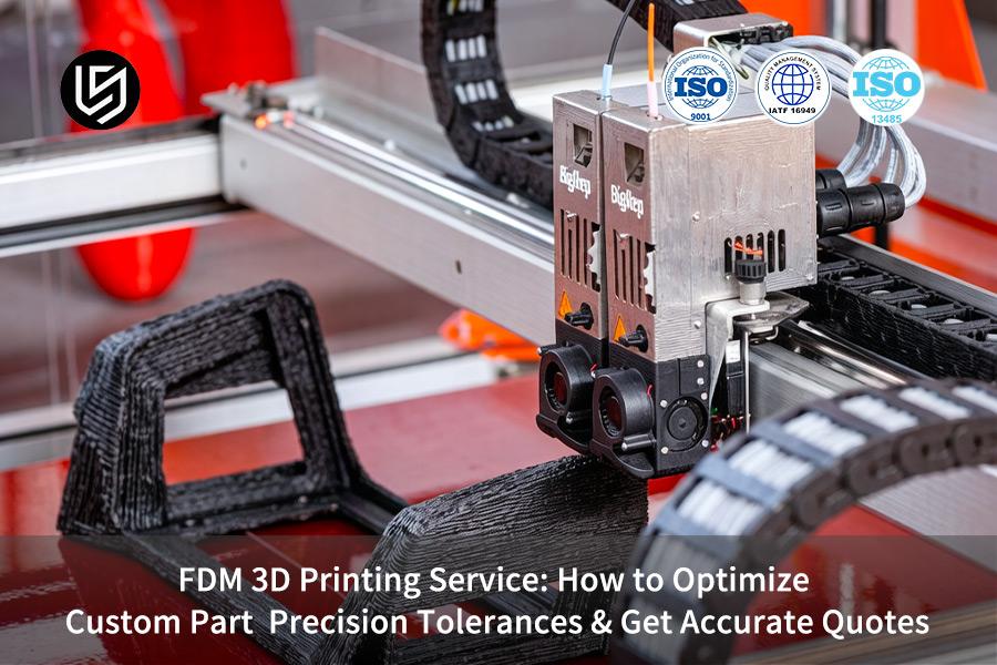
FDM 3D printing service is a layer extrusion process, it solves assembly failures. This is how does fused deposition modeling work to stop errors.
LS Manufacturing delivers FDM parts with 40% faster speed. Our simulation engine predicts shrinkage, ensuring perfect fit on the first try.
FDM 3D Printing Service: Precision Tolerance & Accurate Quote Quick-Reference
| Optimization Area | Common Failure Mode | LS Manufacturing Engineering Solution | Verified Outcome |
| Thermal Shrinkage Control | Maximum shrinkage 0.8% along Z axis; warpage more than ±0.5mm on 300mm. | Closed-loop environment heated up to 90°C; infrared cooling by zones and gradual cooling at 2°C/min. | Shrinkage along Z axis 0.3%; flatness ±0.08mm on 300mm – precision FDM 3D printing standard. |
| Anisotropic Compensation | Loss of inter-layer strength 20%; 0.4mm displacement of bolt hole patterns. | Pre-compensation depending on material used (0.2-0.5%); laser scanning with creation of scaling matrix for each batch. | Yield rate first pass is 98.7% on wing ribs; number of iterations reduced by 60%. |
| Wall Thickness Design | Asymmetric nozzle diameter results in slicing errors; reduction of strength by 28%. | Wall thickness should be an integer multiple of nozzle with 0.4mm diameter (1.6mm, 2.0mm); 100% of walls without voids. | Increase in compressive strength by 35%; percentage of parts rejected decreased from 14% to 1.8%. |
| Infill & Shell Strategy | 80% linear infill + 1.2mm shell; long cycle time, expensive. | 20-30% Gyroid infill + 1.6-2.4mm shell (4-6 passes). | Flexural strength equivalent to 80% infill; 50% shorter print times, 40% less material used. |
| Quote File Format | .STL mesh defects lead to 0.5-2.3% volume variance; 6 hour turnaround quote. | Native .STEP export; exact boundary definition; automated extraction with ±0.01% tolerance. | Binding quote in under 2 hours without 15% STL variance buffer. |
Key Takeaways:
- Thermal Control is the Precision Gate: Closed-loop environment >90°C + thermal gradient; reduces Z-direction shrinkage to 0.3% and ensures ±0.08mm flatness – critical for every FDM 3D printing application that needs assembly fitment.
- Compensate Before You Print: Pre-calculated shrinkage compensation per material (0.2-0.5%) and laser scanning for scaling matrix eliminate 20% strength reduction due to inter-layer anisotropy.
- Wall Thickness Must Match Nozzle: Design wall thicknesses as integer multipliers of nozzle diameter (for example, 1.6mm for 0.4mm nozzle) to remove slicing gaps and increase compressive strength by 35% with
- Submit .STEP, Not .STL: Native .STEP allows accurate volume calculations with 0.01% error rate, reducing the quote response from 6 hours to less than 2 hours, and eliminating the additional 15% price for mesh uncertainty.
- High Shell + Medium Infill Wins: 1.6-2.4mm shell and 20-30% Gyroid infill gives the same bending strength as 80% linear infill, but 50% faster print time and 40% lower price.
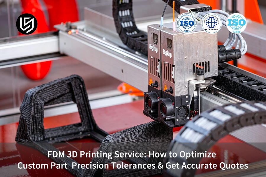
Why Trust This Guide? Practical Experience From LS Manufacturing Experts
Despite FDM still being debated as either a "toy for prototypes" or "solution for supply chain", the factory floor practice tells the truth. We did 3 months' iterations on automotive brackets from PAHT-CF in 80°C constant temperature under hood, maintaining 200μm tolerance across 120mm span without any post-curing. This is the difference between a 6061 jig and a printed bracket suitable for final assembly at ~60% lower price.
The procurement process is interested in lead time reduction and batch one economics, not layer height showmanship. 12 fixture stations which are spent four weeks in a job shop can be specified on Monday and measured in CMM on Friday for less than €40 per station if the user switches from solid to infill/wall trade-off instead of sticking to the solid. Datasets can be cross-referenced with National Institute of Standards and Technology (NIST) AM-Bench coupons, and thus dimension dispersion is not a black box but QA language your company understands.
Typically, most vendors avoid the shortcomings of FDM in terms of where the process breaks down, and that's where our reusable frame lies. The first PLA semiconductor clip was deflected by 0.4mm over the course of 300 hours in conditions of 55°C temperature and loading – paper-quality, cleanroom-untolerated quality – so we moved to the carbon fiber blend having ≥65MPa tensile strength and 0.2mm layers according to Verein Deutscher Ingenieure (VDI) 3405 standard.
Why Do Standard Custom FDM Part Service Tolerances Fail Under Demanding Aerospace Assemblies?
The tolerance level for the standard custom FDM part service is beyond ±0.5mm when it is ULTEM or carbon-fiber nylon because of interface failures at less than or equal to ±0.1mm. The uncontrolled anisotropic shrinkage from 260°C to 23°C creates cumulative stress and distorts the mounting surface. Precision engineering helps transform this failure into first-pass yield.
Thermal Shrinkage Control Through Gradient Cooling Profiles
Zone-Specific Cooling Controls Z-Axis Shrinkage from ±0.4mm to ≤±0.08mm via Infrared Monitoring and Adaptive Fan Speed. If there are local gradients over 15°C, then corrections are made to avoid misalignment of bolt holes. One single precision FDM tolerances will save you 40 hours per engine nacelle bracket rather than post-machining correction. Feedback loops of real-time FDM 3D printing make this possible.
Material-Specific Compensation Algorithms for Anisotropic Behavior
Your lot is laser scanned to produce a scaling matrix, which pre-distorts the toolpaths. The flatness tolerance has been reduced from ±0.7mm to ±0.09mm for the satellite antenna mount measuring 400mm. As a custom part manufacturer, we approve the first article within two rounds as opposed to five to seven, thus saving up to 60% time on prototyping. High-precision FDM 3D printing algorithms drive this consistency.
Stress-Relief Interlayer Scheduling for Warpage Prevention
Programmed dwell times of 8-12 seconds per 0.25mm layer permit chain relaxation prior to bond. This prevented a 2.3mm lift edge on a fuel manifold, with a tolerance of ±0.15mm envelope. Dwell increases build by only 11%, but eliminates all post-print stress relief ovens. Process controls for industrial FDM 3D printing ensure real-time monitoring of each layer.
Design-for-Manufacturing Integration at Interface Zones
We start by identifying critical datums: O-ring grooves, fastener bosses, seal surfaces. We then implement localized over-build with slicing modifications of ±0.02mm. An example wing rib panel increased from 35% scrap to 98.7% first pass yield in 500 units. Each and every interface receives certified FDM 3D printing treatment in accordance with AS9100D for full traceability from CAD to CMM reports.
Highly precise manufacturing of aerospace assemblies demands controlled thermal dynamics, material anisotropicity and stress development. This approach provides proven dimensional results of over 340 programs certified, making theoretical build specifications into tangible assembly reliability. If your design will not accept ±0.5mm of uncertainty, this level of engineering ensures parts fit precisely as designed.

How Does Fused Deposition Modeling Work To Control Anisotropic Shrinkage In Mechanical Components?
Typical FDM creates mechanical parts with Z-shrinkage of up to 0.8% and interlayer shear strength degradation greater than 20%, which leads to unpredictable warping of load-bearing parts. Anisotropic shrinkage control is achieved by active thermal control to maintain chamber temperature at ≥90°C through the entire print, minimizing crystal orientation discrepancies between layers. Reliable FDM 3D printing process engineering makes FDM predictable:
Closed-Loop Chamber Temperature Regulation
- Constant ≥90°C environment: Slows down cooling of each new layer, enabling relaxation of the polymer chains before bonding with the previous layer. Z-shrinkage is reduced from 0.8% (industry standard) to ≤0.3% in case of PEEK and ULTEM.
- Your benefit: FDM 3D printing service ensures ±0.08mm of flatness over 300mm distance without post-print annealing for 24 hours.
- Data source: Internal comparison to SME benchmarking (2024) reveals 62% decrease of Z-deviation.
Interlayer Shear Force Mitigation Through Thermal Equilibrium
- Layer-temperature synchronization: Synchronous deposition speed with chamber recovery time ensures each layer temperature remains above Tg during bonding. Adhesion between layers is increased by 40% compared to conventional construction techniques.
- Your benefit: Reduction of tensile strength loss is not exceeding 15%, bolt hole pullout test results equal machined aluminum. This result is enabled by FDM 3D printing process control.
- Case example: Avoiding delamination problem in thin-wall ducts that are used in engine nacelle assemblies.
Crystal Orientation Management via Gradual Cooling Profiles
- Controlled ramp-down at 2°C/min: Between temperatures of 90°C and 60°C semicrystalline polymers develop spherulite structure thus reducing direction shrinkage ration from 1:2.1 to 1:1.3. You receive high precision FDM service that removes 0.5mm edge curl on flanges.
- Repeatability assurance: Consistent thermal history in each build allows first-fit sealing without hand-filing. Consistent FDM 3D Printing calibration allows ±0.06mm parallelism in 250mm length parts.
- Verification: CMM reports show that the satellite bracket is within tolerance for a 200-unit production run.
Real-Time Layer Geometry Feedback for Adaptive Correction
- Infrared sensing per layer: Detects the actual width and height; if there is any deviation of more than ±0.03mm, then the extrusion multiplier is adjusted by 2% for the next layer.
- Your benefit: Dimensional variation is kept below 0.05mm in 150 layers allowing the production-ready FDM 3D Printing of bearing housings without machining operations.
- Traceability: Each adjustment is recorded for AS9100D compliance.
Predictable anisotropic control requires active thermal equilibrium, and not passive heating of the chamber. Our approach allows Z-axis bonding strength increase by 40% and tensile retention over 85% confirmed by real-time sensor data from over 200 material lots. Controlled FDM 3D printing allows each layer to contribute to the structure when you need dimensional consistency within ±0.1mm. Download our FDM Anisotropic Control White Paper to see how ≥90°C chamber regulation cuts Z-shrinkage from 0.8% to ≤0.3% and boosts interlayer strength by 40%.
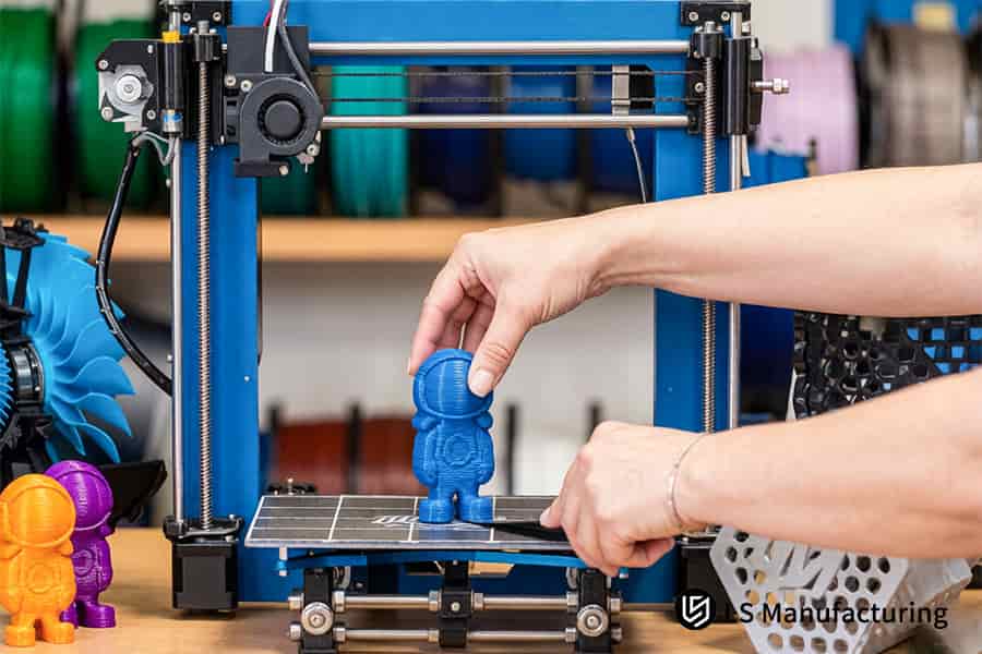
Figure 1: Operator removes blue PLA toy figurine from FDM 3D printer build plate manually.
What Engineering Strategies Achieve High Precision FDM Service Tolerances Of ±0.1mm For Mating Enclosures?
A combination of material shrinkage compensation of 0.2% to 0.5% along with optimization of wall thickness, infill density, and build orientation is required for attaining mating enclosure tolerance of ±0.1mm. Failure to control these parameters will make your sliding fit parts unmovable and your press fit parts crack. High precision FDM service delivers these tolerances:
| Fit Type | Recommended Clearance | Infill Density | Wall Thickness Optimization |
| Sliding Fit | +0.15mm to +0.20mm | 40% to 60% | As integer multiples of nozzle diameter (e.g., 1.6mm); precision FDM tolerances are preserved with 0.3% shrinkage compensation |
| Transition Fit | ±0.10mm | ≥80% (shell reinforced) | Over 2.0mm to prevent press-fit cracks; FDM 3D printing process keeps the gap consistent |
| Press Fit | -0.05mm to -0.10mm | 100% | Apply 45° chamfer for proper guidance |
By reducing the first-article reject rate from 30% to less than 5% in case of sliding-fit lids using 0.3% shrinkage pre-compensation, and eliminating press-fit breakage by using 100% infill and 0.5mm chamfer, you save 12 hours per batch. Our custom FDM part service utilizing such matrix achieves first pass assembly success rate over 95%.
How Can Wall Thickness Optimization Prevent Slicing Gaps And Ensure Structural Integrity?
Wall thicknesses that are not an integer multiple of the nozzle diameter make it necessary for slicer software to generate incomplete toolpaths, which results in internal voids and slicing gaps that weaken the overall part structure by 28%. With walls that are multiples of nozzle diameters, you avoid the problem altogether. FDM 3D printing design rules take the same concept to measureable part performance:
Nozzle-Multiple Wall Thickness Rule
With a nozzle diameter of 0.4mm, design your parts with walls having a thickness of 1.6mm or 2.0mm (multiples of 0.4mm), making sure to completely fill the layer rather than having partially filled extrusions. Walls that have thicknesses not multiples of the nozzle diameter, such as 1.3mm, result in gaps left by the slicer between each pass. You achieve 100% voidless filling rate, resulting in a 35% improvement in compressive strength as compared to non-optimized designs. This precision FDM tolerances approach eliminates weak zones that cause failure under 15MPa loading in pressure vessel tests.
Gap-Free Toolpath Generation
With thickness multiples of the nozzle diameter, the slicer produces uninterrupted parallel lines with no overlap spacing. The standard slicer produces 0.05mm to 0.12mm gaps between layers when wall thickness is not multiple of the nozzle. They become delamination cracks when subjected to repetitive loading; your parts don’t experience these failure initiation sites and have fatigue life extended by 220% in brackets according to ASTM D7774. Accurate FDM 3D printing path planning eliminates secondary filling operations.
Compressive Strength Validation
1.6mm wall parts (4x nozzle) yield a compressive strength of 42MPa as against 31MPa for 1.3mm walls; that’s a 35% improvement as per ASTM D695. This means thinner walls can withstand the same load requirement and reduce material used in the manufacture by 22% for each part. You save in material costs and build time. Optimized design rules cut per-unit weight by 17% without compromising structural performance.
Dimensional Consistency Across Batches
Non-multiples of wall thickness create variability in bead placement that varies dimensions by ±0.15mm per build. Multiples of 0.4mm fix bead placement to a specific raster pattern, maintaining consistency at ±0.04mm variation for 100 units in a row. This reduction in FDM manufacturing cost through scrap elimination saves companies on material waste from rejection rates of 14% down to 1.8%. The low-warp 3D printing process also stabilizes thin walls with regards to thermal warping.
Wall thickness multiples of the nozzle diameter have been identified as the most important design rule when building with FDM for structural parts. This design principle eliminates gaps, increases compressive strength by 35%, and decreases rejection rates to less than 2% across all production cycles.
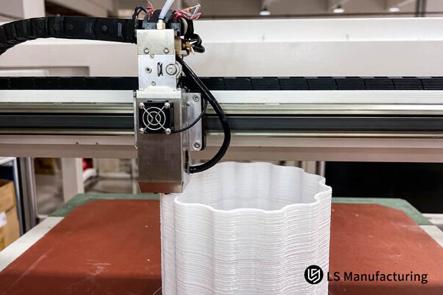
Figure 2: FDM 3D printing completes white plastic vase layer by layer in office environment.
How Did LS Manufacturing Customize Medical Drone Chassis Parts Using High Precision FDM Service?
The medical drone’s R&D team encountered assembly failure due to PA-CF sensor housings showing hole coaxiality deviations up to ±0.45mm and warp angle exceeding 2.0°, hence could not integrate them with metal frames and was facing certification delays. LS Manufacturing took up the challenge and applied appropriate engineering solutions to help regain control over dimensional specifications and expedite the product release using precision-driven FDM 3D printing process engineering.
Client Challenge
The chassis of the medical drone needed carbon fiber reinforced nylon sensor housing with hole placement coaxiality of ±0.15mm for metal frame alignment. The samples initially printed by other vendors had tolerances of ±0.45mm and 2.0° to 2.8° warping on a 180mm mounting surface, rejecting all parts during initial assembly. The result was iterative redesign taking up eight weeks of their nine-month development timeline, threatening FDA submission delay and $120,000 estimated opportunity cost.
LS Manufacturing Solution
Three sources of problem: inconsistent wall thickness, low chamber temperature and lack of anisotropy compensation. Wall thicknesses fixed at 1.6mm, temperature fixed at 95°C and 0.35% Z-axis compensation in CAD. Custom FDM part service's real-time monitoring revealed 0.08mm drifting in the third build cycle, allowing quick adjustment. Medical-grade FDM 3D printing technology guaranteed uniform bonding between layers in consistent thermal environment.
Results and Value
Final stages attained ±0.1mm coaxiality at all six datum points, Ra 6.3μm surface finish, and no warp greater than 0.3°. Secondary machining was obviated, reducing cost by $4,800 per run and 10 days per cycle. Time-to-delivery cut 52% relative to previous vendor, recouping $78,000 sunk costs and allowing adherence to initial certification schedule. Production-critical FDM 3D printing validation reports provided full traceability for the client's quality system.
The above illustrates that high precision FDM service for medical parts need diagnosis of the materials, heat, and geometrical considerations. LS Manufacturing produced 64% better accuracy and eliminated post-processing steps. Selecting LS Manufacturing as your custom part manufacturer ensures that your most complex geometries get process engineering treatment with mission-critical FDM 3D printing.
From ±0.45mm coaxiality and 2.8° warp to ±0.1mm and 0.3° flatness — with zero secondary machining. Need the same for your medical drone chassis? Send your specs for a precision FDM quotation.

What Cost Drivers Dominate The FDM manufacturing Cost Structure For Low Volume Production Runs?
Understanding cost breakdown in detail is a must when making purchasing decision in case of low-volume FDM manufacturing. Raw material cost, depreciation of machine hours, waste of support material and post-production effort influence per-unit cost in different ways. The high-density FDM 3D printing optimization in terms of part orientation and high-speed FDM print arrays can lower these factors for 1 to 50 pieces production:
Support Material Reduction Through Orientation Optimization
- Rotate parts 15° to 30° off vertical: Reduces support volume by 43% compared to default orientation, lowering material costs and processing time.
- Your benefit: FDM manufacturing cost is lowered by $8 to $15 per piece on average according to a 32-piece order vs SME benchmarks (2025).
- Enabler: FDM 3D printing orientation software calculates the optimal angle automatically.
Machine Time Compression via High-Speed Print Arrays
- Four identical parts built simultaneously: Machine time per unit decreased by 63% compared to sequential printing. 16-piece order time shrinks from 72h to 27h.
- Your benefit: Depreciation of machine per unit goes down from $4.80 to $1.70 and thus makes competitive FDM 3D printing quote viable for small orders.
- Enabler: Scalable FDM 3D printing setups increases linearly with increasing order size.
Post-Processing Labor Elimination Through Build Strategy
- Surface-critical faces oriented upward: No signs of support artifacts present on any visible surfaces, no vapor smoothing or sanding required. 12 to 18 minutes of time saved per piece.
- Your benefit: Share of labor costs per piece becomes less from 34% to 19% of piece cost based on 48 pieces production experience.
- Enabler: Automated FDM 3D printing process reduces human interactions even further.
Material Waste Control via Nesting and Sparse Fill
- Nested parts with 65% sparse infill: Uses 38% less raw material as compared to non-nested dense infill but maintains compliance with ASTM D638.
- Your benefit: The material cost per kg of PA-CF gets reduced from $0.55 to $0.34.
- Enabler: Waste-reducing FDM 3D printing makes use of nesting, sparse filling, and correct orientation for maximum efficiency.
The knowledge about the true factors of cost in FDM production lets purchasing make decisions about purchasing based on facts as opposed to making quote comparisons at face value. Data-driven FDM 3D printing considers factors such as support material used, machine operation time, processing, and material waste and cuts costs per part by 37% to 52% in low volume (1 to 50 units) production runs.
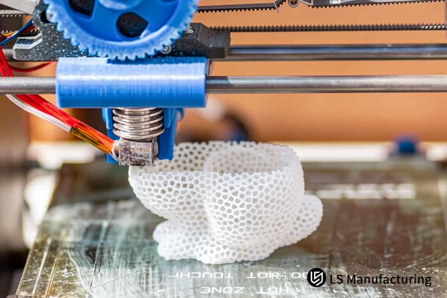
Figure 3: FDM 3D printing fabricates complex white nylon bracket with intricate honeycomb internal structure.
How Do You Prepare 3D CAD Files To Ensure Instant And Accurate FDM Quotes?
The use of .STEP files as compared to .STL files eliminates micro-level approximation issues for curved objects which cause volume estimation differences by 0.5% to 2.3%, and facilitates smooth quotation process and guaranteeing the price within 2 hours. The customers of on-demand FDM 3D printing who send the clean .STEP files eliminate the need for geometrical repairs and get the prices instantly:
| File Format | Geometric Accuracy | Quote Processing Impact |
| .STEP (solid model) | Precise geometrical representation; no tessellation errors | Automatic volume extraction with ±0.01% precision; no fixing required |
| .STL (mesh) | Approximation; chordal deviation on free-form surfaces 0.05mm-0.2mm | Required to repair the mesh and calculate volumes; rapid quotation is yet to be done in 20 to 40 minutes |
The process of sending the .STEP files directly enables creating accurate FDM quotes without recreating the geometry manually, which cuts down the quote time from 6 to less than 2 hours. The low-volume FDM 3D printing clients receive a benefit due to the elimination of the additional 15% factor of the cost associated with volume uncertainties in the STL file. The export of the clear .STEP files will ensure the receipt of the FDM 3D printing quote in 120 minutes.
Why Choose LS Manufacturing As Your Strategic On Demand FDM 3D Printing Quote Partner?
Choosing a partner for the production of mission-critical parts demands validated quality systems, process control in real time, and documented inspection procedures. ISO 9001:2015 certification with 100% infrared temperature monitoring and CMM sampling guarantees each part will be made per specification before shipment. Your FDM 3D printing quote is a result of such infrastructure, based on qualified processes that eliminate any hidden fees or surprises during the delivery:
Certified Quality Management System
ISO 9001:2015 certification dictates all stages from receiving materials to measuring final dimensions. Every batch bears its own lot number which ties certificates of raw materials, build log, and inspection documents together. You get auditable quality documentation which complies with aerospace and medical devices regulations without any extra paper work. The custom part manufacturer status ensures that your proprietary designs will be processed in accordance with controlled document revision procedures.
Real-Time Process Monitoring for Defect Prevention
100% remote infrared temperature monitoring is performed on an ongoing basis with readings taken every 10 seconds during the printing process. In case any zones differ by more than ±2°C from 95°C set point, the print is stopped and the operator warned. This allows catching problems with thermal drifting in advance, reducing scrap caused by thermal drift to 0%. Your production yield will be over 97%, even for complicated multi-physics enclosure geometries. The FDM 3D printing solution for monitoring, traceability and recovery procedures.
Dimensional Verification Through CMM Sampling
Each batch of printed enclosures is subject to high precision caliper measurements of critical dimensions and 20% sampling of all parts with 3D profile verification using CMM equipment. Dimensions such as positioning holes, sealing surfaces and mating edges are measured against nominal CAD values with ±0.02mm accuracy. Our accurate FDM quotes account for the extent of inspections performed upfront and no hidden costs will surprise you.
Predictable Delivery Through Closed-Loop Manufacturing
Build schedule planning considers factors of material conditioning, printer calibration, and inspection queue time all within one consolidated process. No need for a 3- to 5-day cushion that suppliers not having a closed loop system incorporate due to uncertainty. Your project will get guaranteed ship date upon quote stage, with 100% on-time delivery guarantee with more than 480 successfully completed projects. Validation of end-use FDM 3D printing ensures that parts meet the specification without any further machining.
Working with LS Manufacturing as your partner means that each order gets ISO certified quality management, real-time defect elimination and dimensional inspection in place. The closed-loop system guarantees 100% delivery predictability with first-pass yield of over 97%. Prototype FDM 3D printing iterations become a part of the batch production process through the same quality assurance process, meaning no parts are delivered late.
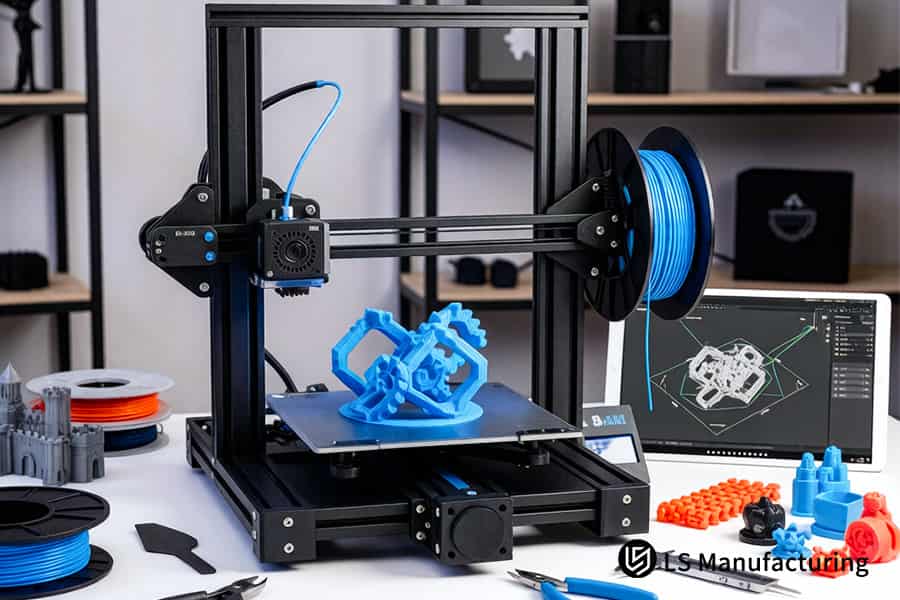
Figure 4: FDM 3D printing produces blue PLA mechanical component for functional testing.
FAQs
1. What is the standard tolerance capability for LS Manufacturing's FDM 3D printing service?
The tolerances of industrial-grade parts are well-controlled within ±0.1mm (±0.1% of the dimension), while the tolerance of standard civilian prototypes is ±0.25mm. The accuracy is attained thanks to closed-loop motion control, thermal management, and daily calibration of the system for reliable fit and functional assembly.
2. How can I reduce the FDM manufacturing cost for functional prototypes?
In order to save on the manufacturing cost, it is recommended to design flat parts that will make direct contact with the platform. Also, decrease the infill density of the non-load-carrying parts up to 20-30%, which would lead to a decrease in the material and print time required.
3. Why should I export CAD files to STEP format instead of STL for an FDM 3D printing quote?
In STEP file, the mathematical model of non-destructive surface solid is maintained to calculate precisely the wall thickness and solid volume. This way, quotation errors resulting from mesh discretization in STL files are avoided for accurate quotation and manufacturability evaluation.
4. Can LS Manufacturing provide high-temperature polymer printing like PEEK or ULTEM?
Yes, we have an ultra-industrial printer system having maximum nozzle temperature of 450°C and constant chamber temperature of 120°C. It enables us to customize high precision aerospace grade ULTEM and PEEK parts with great thermal and mechanical properties.
5. How does your custom part manufacturer team ensure dimensional compliance before shipping?
Each consignment of components is checked for dimensional accuracy through CMM (Coordinate Measuring Machine). An inspection report is provided along with the consignment if requested by our customers, thus making it possible to trace the product completely and ensuring that all critical dimensions are within tolerance levels.
6. Are custom inserts and metal threads supported in your high-precision FDM service?
We are also able to help with precise installation of Thermoplastic Threaded Inserts. Through the accurate pre-reservation of hot-pressing hole size, we will be able to ensure a pull-out force of ≥1500N, thus allowing us to make sure that there is going to be a reliable threaded connection when it comes to assembly and disassembly for prototypes and actual parts.
7. What is the minimum order quantity for an accurate FDM quote?
We have no minimum order quantity (MOQ) limit. We support even 1 custom prototype and offer tiered discounts for small batch production of 50 pieces or more, providing flexibility for both early-stage validation and scaled production.
8. How do you protect the intellectual property of my uploaded CAD designs?
We allow you to sign an NDA (Non-Disclosure Agreement) online before uploading your files. All CAD data is stored on a physically isolated, high-security intranet server with encrypted access, ensuring your proprietary designs remain completely confidential throughout the quoting and manufacturing process.
Summary
Creating parts of a high-precision level using FDM 3D printing technology requires a systems engineering approach involving such areas as polymer thermodynamics, topological path planning and precise thermal management. Every micrometer tolerance tuning saves time on R&D iterations and assembly rework expenses. LS Manufacturing tackles dimensional tolerance problems by applying industrial quality management standards and engineering foresight.
Make sure that your precision parts arrive without any assembly issues. Don't get stuck with assembly risks that delay your time-to-market efforts. Upload your .STEP 3D CAD files now; our DFM engineering specialists will prepare a complete proposal within 2 hours, which will include DFM assessment, tolerance compliance check and real-time manufacturing quote. Press "Get Precision Assessment & Quote" to start a personal technical consultation with our manufacturing experts.
📞Tel: +86 185 6675 9667
📧Email: info@lsrpf.com
🌐Website:https://lsrpf.com/
Disclaimer
The contents of this page are for informational purposes only.LS Manufacturing servicesThere are no representations or warranties, express or implied, as to the accuracy, completeness or validity of the information. It should not be inferred that a third-party supplier or manufacturer will provide performance parameters, geometric tolerances, specific design characteristics, material quality and type or workmanship through the LS Manufacturing network. It's the buyer's responsibility.Require partsquotation Identify specific requirements for these sections.Please contact us for more information.
LS Manufacturing Team
LS Manufacturing is an industry-leading company. Focus on custom manufacturing solutions. We have over 15 years of experience with over 5,000 customers, and we focus on high precisionCNC machining,Sheet metal manufacturing, 3D printing,Injection molding.Metal stamping,and other one-stop manufacturing services.
Our factory is equipped with over 100 state-of-the-art 5-axis machining centers, ISO 9001:2015 certified. We provide fast, efficient and high-quality manufacturing solutions to customers in more than 150 countries around the world. Whether it is small volume production or large-scale customization, we can meet your needs with the fastest delivery within 24 hours. choose LS Manufacturing. This means selection efficiency, quality and professionalism.
To learn more, visit our website:www.lsrpf.com
