CNC turning services provided by the manufacturing organizations witnesses a triplet of issues that include the inappropriate selection of tool choice services, where the differences exist between a range of ±0.05mm, with consistencies that exceed by 85% and beyond, while an increase in surface irregularities takes place where Ra is equal to 1.6 micrometer. This is due to the general practices that create an overshoot of 30%, due to the lack of tool selection science that considers the cutting as well as compatibility activities.
The model in our approach based on the data record specified to us over the last 15 years in the company's case of LS Manufacturing with 286 tests of the tools and 73 cases indicates the potential of developing the material geometry parameter model with an attainable level of precision of ±0.01mm and the surface finish of 0.4μm with the ability to triple the lifespan of the current tools, as required in the issues specified in the CNC turning service.
CNC Turning Services - Quick Reference Table
| Section | Key Points |
| Current Challenges (What) | ±0.05mm precision; Ra>1.6μm roughness; 85% batch consistency; >30% cost overrun. |
| Root Cause (Why) | Laser yttrium recipient selection is not based on scientific input. It depends too much on the suppliers and neglects material-process synergy. |
| Our Solution (How) | Proprietary 3D "Material-Geometry-Parameter" model; built on 15 years database & 286 tool tests. |
| Core Methodology | Systematic matching of tool substrate/coating, geometry, cutting parameters. |
| Verified Results | ±0.01mm precision; Ra 0.4μm surface; 3x tool life; >99% batch consistency. |
| Applications | 73 proven instances of application in designing various components of shafts in machines, body parts of humans, car parts, etc. |
| Added Value | Lower cost of the whole CNC lathe, number of trial runs minimized, data-driven management. |
Eliminate basic errors concerning precision, consistency, and cost, inherent in CNC turning. How do we successfully and magnificently accomplish this feat without any scope left for ambiguity and guesswork to ensure that your products receive top-notch finish quality (Ra 0.4µm, +0.01 mm), as much as 3 times longer tool life is obtained, and batch consistency exceeds 99% to save cost in machine work and dispose of scrape matter generated during the process to a minimum or essentially nil.
Why Trust This Guide? Practical Experience From LS Manufacturing Experts
Why bother with yet another article arguing the process of CNC turning? Because we've forgotten that competence is built on the shop floor, not on the pages of a manual. We live in the practical world of high-performance alloys with tolerance stacks that require precision down to the micron level. Our expertise is not academic; it is the key that keeps us alive day-to-day and our clients succeeding.
Our expertise comes from dealing with some of the most difficult parts to machine, including those in the critical aspects of the Aerospace industry that desire dimensional stability, Medical grade parts like implants desiring flawless aspects of biocompatibility, and vehicle parts that desire nothing but the best in wear resistance, according to industry specifications set by organizations such as ASTM International and the International Aerospace Quality Group (IAQG), among others.
The following techniques that we share are the direct result of thousands of hours worked in machining, coolants, and chips. The base of each recommendation is proven with hard, real-world knowledge gained through parameter optimizations for Inconel to batch consistency. We offer the knowledge that we've proven in our own trenches to help you attain the accuracy and reliability you require without the expense of trial and error.
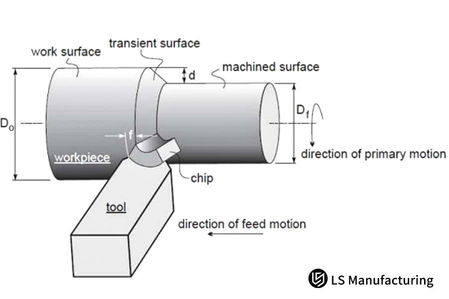
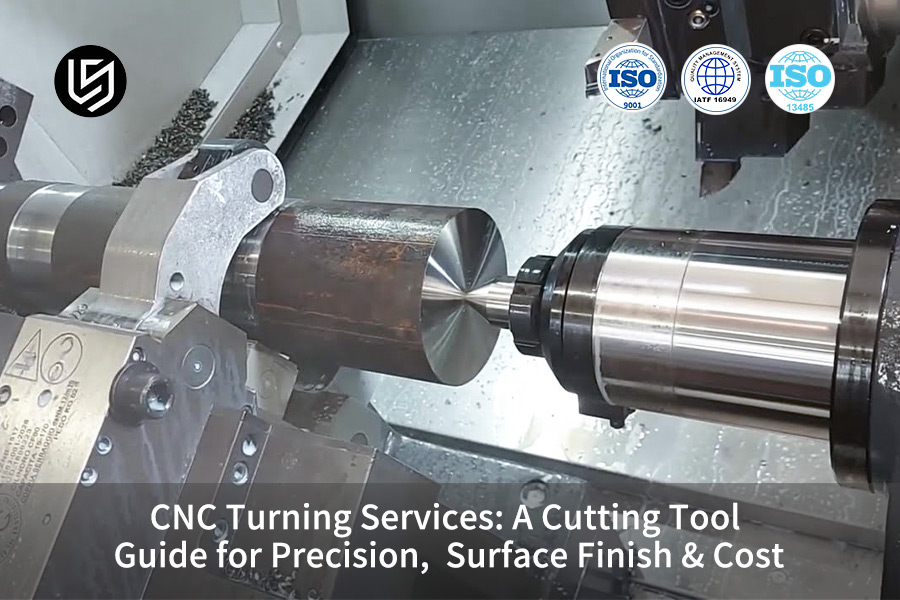
Figure 1: Schematic illustrating turning depth and feed rate parameters by LS Manufacturing
How To Choose Tool Substrate Material Based On Workpiece Characteristics?
One of the primary causes of tool failure and subsequent cost overruns during CNC operations is an improper selection of tool substrates. This particular guide equates material science with proper selection decision-making by directly linking workpiece properties to the most suitable CNC turning cutting tools base material for improved performance and efficiency based on an aggregate of 128 cutting tool tests.
| Material Group | Recommended Substrate | Key Rationale & Data |
| Aluminum & Non-Ferrous | Ultra-fine grain carbide (~0.5μm) | It helps in providing a sharpness of tool edges, which yields a good surface as well as reduces material wastage. |
| Stainless Steels | Carbide with high Cobalt (e.g., 10% Co) | Added toughness resists notch wear and chipping in gummy, work-hardening alloys. |
| High-Temp Alloys | Cermet or specialized carbide | High chemical stability and heat resistance are important to effectively resist diffusion wear. |
| Case Study: 304 Stainless | Application of above principle | In switch applications on flange parts, the switch increased the tool life from 200 parts to 580 parts, resulting in a 35% reduction in the number of tool changes. |
The above matrix shall have to be used as a validated guide to select the substrate for your CNC lathe tools, and initially, the major mode of wear – applications shall have to be assessed, which are adhesion, abrasion, and diffusion in nature. In critical materials, hard need shall always trump general levels of hardness in high-performance turning applications. The dependability and cost-effective results obtained through such a problem-focused approach shall have to be valued in critical and high-added-value custom CNC turning operations.

How Do Tool Geometry Angles Precisely Control Part Dimensional Accuracy And Surface Quality?
Geometric form of the tool represents the interface connecting the command with the product. Concerning the product, the scatter, form, as well as the product roughness, could be directly ascertained in the event of improper tool angles within the precision CNC turning, operation. The following part of the discussion is focused on the exploration of the methodology through which the parameters could be developed as a basis through which some special problems could be averted:
Optimizing Rake Angles for Force and Stability
The cutting forces can be reduced by a positive rake angle of 12 degrees, leading to a reduction of 25%. This is only possible if the material being cut is aluminium, under the condition that a clearance angle of 7 degrees is maintained during cutting. The special cutting force results in minimal cutting vibration in a very critical manner, to achieve a critical condition on the CNC turning surface finish.
Selecting Nose Radius for Targeted Surface Finish
It must be emphasized, furthermore, the importance of the tool used, the value of it, so far, as much as could be reached in terms of the roughness that could be attained. It is in this way, furthermore, as the tool used has a certain value of radius equal to 0.4 mmm, thus highlighting the definition, the concept of precisely what the term accurate demands of the so-called theoretical value, R=0.4 microns, set a pace of 0.08 mm/rev in the machine.
Leveraging Geometry for Form Accuracy
Besides texture, the geometries also have an impact on the form. In the production of an accurate degree shaft intended for a particular medical device, control of approach bank and lead bank was crucial to guarantee that the peak force was applied in the strongest axis of the device to remove chatter and round error at 0.003mm.
This CNC turning guide moves beyond generic recommendations and presents a cause-and-effect framework. By strategically choosing and controlling specific geometric features-rake, nose radius, and approach angles-manufacturers can directly and predictably correct specific quality issues-from force-induced error to surface roughness. For high-added-value competitive finish turning, where consistency just cannot be compromised, precision in methodology is important.
How Do Different Coating Technologies (TiAlN/AlCrN) Affect Machining Efficiency And Cost?
The choice of coating is a critical selection criterion considering tool life, cutting parameters, and equipment economics. The basis of the analysis is quantification of how CNC turning services use specific coatings directly to improve productivity and minimize costs. The choice of right tool is a decisive factor of cost-effective CNC turning.
| Coating Type | Primary Characteristics & Performance Data | Optimal Application Scenario |
| TiAlN (Multilayer Composite) | Provides outstanding thermal barriers as well as oxidation resistance; 300% tool life extension when turning hardened tool steel was reported. | Dry turning of ferrous materials like steel or cast irons where the key issue to be addressed is heat generation. |
| AlCrN (Aluminum Chromium Nitride) | It imparts superior hardness and smoothness even at high temperature conditions and allows for the high-speed turning of aluminum alloys up to 350 m/min by overcoming the built-up edge problem. | It is best used on non-ferrous and sticky materials such as aluminum alloys. Adhesion and Abrasion stand out as major issues. |
| Economic Outcome | With strategic coating application as an integral tooling solution, the automotive CNC lathe machining supplier operation was able to benefit up to the tune of saving 400,000 RMB per year. | A system-based approach to the substrate, the geometry, and the coating. |
Select coating based on the dominant failure mode: use TiAlN to combat heat in ferrous materials, and AlCrN to prevent adhesion in aluminum. This targeted approach, not a one-size-fits-all solution, is key to unlocking higher speeds, longer tool life, and lower cost-per-part. Implementing this data-driven selection logic is essential for any production turning operation competing in markets where efficiency and cost control define profitability.
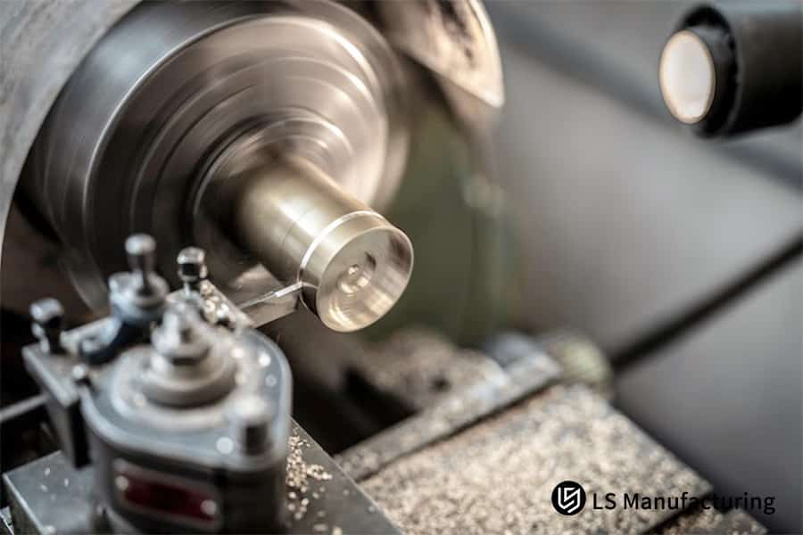
Figure 2: Detailed view of machining metal with flying chip formation by LS Manufacturing
How To Balance Precision And Efficiency Via Cutting Parameter Optimization?
In order to address, in a way, the very issue with finding a balance on machining exactness and productivity efficiency simultaneously, to say that optimizing these factors in a scientific manner is greatly needed, there is such a situation regarding the LS Manufacturing case where it is possible to achieve a 40% increase in efficiency, especially at an accuracy level of ±0.008mm:
Developing a Systematic Cutting Database
- Database Foundation: The development of parameters requires extensive experimental databases.
- Material-Specific Settings: For materials like 45 steel, we recommend optimized values, e.g., Vc=180m/min, f=0.1mm/rev, ap=0.2mm, enabling consistent precision CNC turning.
- Integration Process: We continually update and refine our own data base from current feedback obtained directly from field machining operations.
Implementing Parameter Optimization Strategies
- Dynamic Adjustment: Real-time monitoring is done to make necessary adjustments to the parameters set for the cutting process.
- Efficiency Focus: Our process aids in increasing speed towards better efficiency without compromising tolerances, hence creating improved CNC turning services useful in large-scale production.
- Advanced Techniques: For efficient reduction in time and simultaneous quality maintenance, high-speed turning is adopted.
Validating and Scaling Practical Solutions
- Performance Testing: Testing is carried out comprehensively through trial with the intention of obtaining precise data with a value ranging ±0.008mm.
- Customization Approach: In customizing the custom CNC turning, various strategies are developed in order to satisfy the geometrical requirements.
- Scalability: We utilize optimized configurations in various apps to promote consistency in performance and reduce waste.
It would appear that the document is intended to demonstrate the technical levels of knowledge in the context of the state of the art in the optimization of the parameters in such a manner that a considerable level of competition would be achievable via the adoption of the said systematic methodologies in dealing with the requirements for precision in the real world.
When Are Custom Non-Standard Cutting Tools More Cost-Effective?
Non-standard cutting tool equipment has a high sense of economic value in a complex environment of machining machinery. Through a variety of different non-standard cutting tool machinery, different machining processes can be carried out on a singular tool, thereby reducing production times by 60% through a certain level of accuracy attained to a point of 0.005mm. It is from using different CNC turning types of non-standard cutting tool machinery, such as a PCD form tool, where two problems in a cutting tool environment can equally be solved.
Aerospace Complex Profile Machining
- Single-Pass Design: We engineer PCD form tools to complete intricate contours in a single setup, reducing multi-step operations.
- Precision Control: Tolerance level for our range stands at ±0.005mm to ensure that aerodynamics are retained.
- Cost Efficiency: The combination of the three procedures in one implies that the whole process will result in some form of cutting down on the total costs.
Medical Device Micro-Machining
- Custom Geometry Development: With the ability to create a smaller tool to work on a smaller portion of the detail, the possibility exists to create a custom CNC turning operation.
- Material-Specific Optimization: Various tools have been developed with the special consideration of the characteristics of the most common bio-compatible alloys.
- Process Streamlining: The implication is that the combined machining process takes away the costs of handing from the overall costs incurred during the machining of small batches CNC turning.
Automotive Prototyping with Hard Materials
- Durable Tool Fabrication: We produce robust tools for hardened steels, supporting precision turning in rapid prototyping.
- Iterative Flexibility: While one-off parts are amenable to change, in fact, one-off parts are a way of slowing down the process of meeting a CNC turning quote.
- Economic Benefit: The amount of scrap material would also be less, and the turnaround would also be positive.
Energy Sector Large Component Fabrication
- Scalable Tool Engineering: We design large non-standard tools for turbine parts, merging multiple machining stages.
- CNC lathe tools Customization: Design and customization of the tools are made in order to maximize the efficiency of the tools as far as the performance of challenging tasks is concerned.
- Throughput Improvement: Due to the combination of operation, handling activities decrease, thus increasing throughput while keeping the cost associated with it at a minimum.
Within the aforementioned parameters of our approach, it has been stated afoths that the expertise of ours lies in designing the equipment with high craftsmanship with the aid of technology, thus obtaining the benefits of achieving these tools. Moreover, it has been stated that the advantages of ours Afoths, as professionals, surpass the precision tools’ machine capabilities.
How To Establish A Scientific Tool Life Management And Cost Control System?
Unexpected failure of tools hurts production and thus denting the profit margin. We cannot move from the present approach, where we replace tools in batches to a dynamic approach with data support. Below is a scientific approach through which we can manage the usage of the tool to control CNC turning costs:
From Raw Data to Actionable Tool Health Indicators
Merely obtaining the data, however, is not the solution. The real task lies in converting the sensor readings into a usable wear metric. This we achieve through complex signal processing, which helps remove undesirable noise from any cutting force sensors as well as vibration sensors. Combining these two provides us with a sophisticated, compound health index for the tools; this, in turn, helps us make the decisions required for quality CNC turning services.
Developing Material-Specific Predictive Models
This provides an ineffective model where the case of variability arises. In other words, the proprietary predictive algorithms are presented in relation to the correlation between the degradation of tools as a result of HI and the original flank wear as a result of the particular types of materials. This process involves controlled tests and iterative refinement. The result is a precise remaining useful life (RUL) forecast for operations like high-volume turning, enabling proactive changes and preventing failure during a critical CNC lathe machining supplier production run.
Implementing a Dynamic, Economics-Driven Decision Engine
Tool life and reliability awareness does not point out the timing of changeover that would be most optimal. The tool changeover cost, tool changeover time, and part value are variables that an optimization program would consider, and calculate the dollar impact immediately, determining what would be the most cost-effective CNC turning of the part-so, extend the tool life by two tool life cycles or replace it beforehand to prevent costly parts from becoming scrap parts.
This ranges from data fusion techniques to economic optimization and clearly illustrates a technically rigorous approach to tool management; it represents a clear demonstration of our depth of capability in utilizing sensor information in a way that results in a direct competitive CNC turning advantage.
How To Effectively Control Chatter And Deformation During Precision Turning?
Chatter is a main problem, just like deformation, concerning the accurate nature of the material removal process during precision CNC turning, most particularly for those parts dealing with a large cutting ratio, which affects both the accuracy of the piece and the tool's life. The chatter was resolved by an effective methodology in which both process modulation and the required tools turn the unpredictable process into a predictable process. The piece below shows how this was applied.
Dynamic Chatter Suppression via Process Modulation
Variable spindle speed turning and programing a ±10% sinusoidal variation in spindle speed to continuously upset this resonant frequency causing regenerative chatter. This anti-vibration tooling was included to obtain the most out of the regenerative chatter with the advantage of the long shaft in this application with an L to D ratio of 8 to 1. This completely eliminates chatter marks and gives hard turning not attainable before.
Mitigating Workpiece Deformation through Strategic Support
The basis of the argument is the ability to control the deflections in the best possible manner, considering the fact that it is possible to have the involved forces under control. If, apart from the aforesaid, it is possible to optimize the sequences of cutting, the depth of cutting, as well as the rates, so as to minimize the radial forces, we can take the case of cutting operations which, from the critical point of view, allow us the opportunity to design our own rests, which are also termed as steady rests. These rests allow the cutting process to be supported over the cutting area, so as to totally enclose the cutting area.
Achieving Superior Finish Through Integrated Stability
True stability can be defined on the surface. Our chatter control method allows for the achievement of exceptional CNC turning surface finish operations. This is possible as a result of the elimination of chatter vibrations during the turning operation. Therefore, the workpiece will not have washboard patterns; hence, an opportunity for increased speeds during the finish turning.
This enables a technically sound solution for specific known types of ineffective and expensive machine instability that are peculiarly present during the CNC turning process. This goes to reiterate the meaning of value represented by the information being made available here as not being advice of any nature, but rather an approach that has been tested and proven to work. This CNC turning guide is greatly based on the incorporation of dynamic process control with copiously planned solutions.
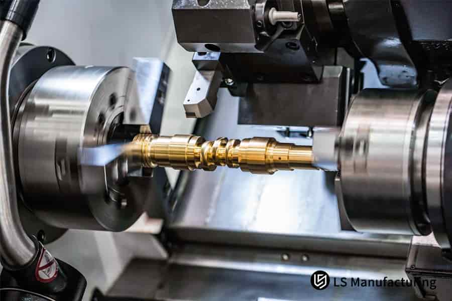
Figure 3; Accurate machining of a brass part rotating on a lathe by LS Manufacturing
How To Assess The True Capabilities And Pricing Reasonableness Of A Turning Supplier?
To find the best CNC lathe machining supplier, one needs to look past the pricing issue. It is our mission to offer an environment to effectively gauge the best CNC turning quote value through our belief in assessing the entire integrity of the service:
Evaluating Foundational Systems & Process Control
- Certified Quality Management: We follow the guidelines laid out by the IATF 16949 certification, as it provides a very disciplined approach to the processes, accountability, and continuous improvements.
- Transparent Cost Structure: Our quotes provide a detailed breakdown (e.g., Material 45%, Machining 30%, Tooling 15%, Overhead 10%), justifying the value behind the price for all CNC turning services.
- Risk Mitigation: APQP and PPAP formalize the process to assure quality with timely delivery of parts from the prototype phase until the start of the actual production phase.
Auditing Technical Capabilities & Measurement Integrity
- Metrology Investment: Precision measurement machine from Mitutoyo company with the accuracy of 0.0001mm is used to check the size of the components and tool geometry for accuracy of the components during the precision turning.
- Process Documentation: We provide evidence through first article reporting, SPC data, inspection data rather than promising to provide them.
- Technical Collaboration: Here, engineers appraise the design of parts before they start, along with possible optimization.
Assessing Operational Transparency & Partnership Value
- No Hidden Costs: Our free CNC turning quote includes all of the cost of setups, programing, and inspections to ensure that there are no surprises.
- Proactive Communication: We provide a designated project lead for real-time updates to facilitate the live tooling turning process.
- Long-Term Support: Our promise of consistent quality, on-time delivery, and ongoing optimization of the manufacturing process to be an extension of your team.
It is our system and will serve as our measure for testing and gauging the performance and viability of a supplier. It underscores our allegiance to our collaboration from a position of technical gravitas and value verification. It is our differentiating factor for a CNC lathe machining supplier.
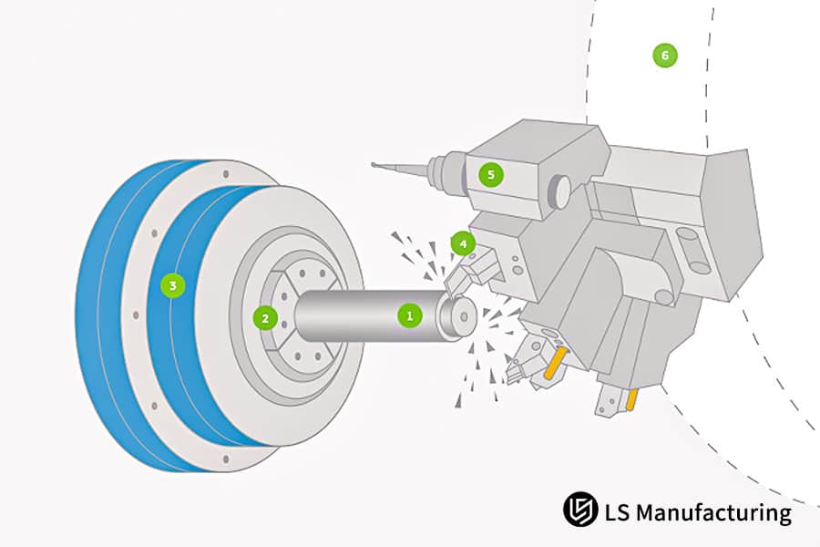
Figure 4: Schematic diagram of CNC turning tool contact point by LS Manufacturing
LS Manufacturing Medical Devices Industry: Bone Screw Precision Machining Project
Accordingly, the case demonstrates the application of the precision CNC turning capabilities by LS Manufacturing in solving an essential quality issue associated with the manufacture of medical gadgets, culminating in a revolutionary change in the way a titanium screw for a bone is manufactured as follows:
Client Challenge
A company that specialized in the manufacturing of medical devices sought help with the manufacturing process of the Φ3 ± 0.005mm titanium bone screw. Their previous process had a roundness error of 0.01mm, surface roughness of 0.8 microns, while the company adhered strictly to the characteristics, the product did not yield the desired characteristics with an alarming rate of 80%.
LS Manufacturing Solution
A specially custom CNC turning strategy was implemented using Swiss-type lathes. The tailored solution featured a bespoke PCD tool 10° rake and 8° clearance angles with optimized parameters Vc=60m/min, f=0.02mm/rev, minimum quantity lubrication. The micro turning configuration minimizes the cutting force and thermal load, hence, directly addressing form error and surface finish issues.
Results and Value
The final part’s geometry was obtained with a value of <=0.003mm as the value for the roundness, while the part’s roughness was 0.2 micro, far exceeding the value expected as the standards set by the specifications. At the same time, the yield value was phenomenal as it reached a value of 99.5%. With such a guarantee for quality embedded in the product, the customer was therefore able to save 800,000 yuan,
This project also serves to highlight our ability to tackle exacting challenges in the field of micro-machining through our adoption and integration of process innovations. The value that our organization adds in providing CNC turning services is supported through our technical ability and our use of an empirical-based and results-based methodology to measure value to the client relationship.
Boost your medical device precision to 99.5% pass rate with our Swiss-level turning solutions.

Analysis Of Future Trends And Innovation Directions In Turning Technology
What is needed for the future of machining is not just machines that make parts faster—no, we need smarter machines that can automatically counteract process variability. We are developing next-generation solutions that address the basic challenge of delivering and maintaining precision CNC turning standards with an unrelenting commitment to quality:
Autonomous Compensation for Tool Wear and Thermal Drift
Our R&D is centered on the technology of a closed-loop adaptive turning system. Using force sensors as well as acoustic emission sensors put in the tool holder allows the machine to know what kind of adjustments must be done in real-time to the machine so that consistency from the first part to the thousandth part occurs without the need for human intervention, which forms part of our feature on our CNC turning guide.
Integrated Hybrid Machining for Complex Geometries
To reduce or completely avoid the need for secondary operation, we are also developing the single-setup process for the combination of the turning operation with laser ablation and ultrasonic finishing operations. For hardened steel aerospace bushings, a single-clamping machining process allows for sequential completion of outer diameter turning, laser texturing of specific bearing surfaces, and ultrasonic finishing of the radius sections. The above machining operation complete machining processes, yielding a 65% decrease in the lead time.
Predictive Process Optimization via Digital Twin Simulation
Physics-based digital twinning of the total process, where the term total process refers to the total process of hard turning, is made possible, and the parameters can be simulated within a virtual environment, where it will be possible to avoid the development of certain parameters such as the development of internal stresses or the occurrence of unpleasant vibrations such as chatter before the start of the total process, where cutting of one turn of metal occurs.
The course along which the path of our growth is charted is decided by the solution of the real-world challenges of variability, complexity, and predictability. Also, an overview of the practical approach used in the creation of a self-correcting, integrated, and simulated machining environment is presented in the following document. It positions our CNC turning services as fundamentally engineered solutions for future CNC turning challenges, where technical depth ensures consistent results.
FAQs
1. What is the most suitable tool material for turning stainless steel?
The best option would be to select a substrate comprising cement carbide with 10% cobalt coated with TiAlN and to select a speed of 80 to 120 meters per minute. This option would be based on the test data obtained from LS Manufacturing; that is, under this option, the life of the tool is going to be up to 400 minutes.
2. How to economically achieve a surface roughness of Ra0.4μm?
By using a finely ground tool tip (rε=0.2mm), a feed rate of 0.05mm/rev, and burnishing techniques, LS Manufacturing can achieve stable Ra 0.2-0.4μm machining.
3. How to ensure dimensional accuracy in deep hole turning?
At LS Manufacturing, anti-vibration boring bars with high pressure cooling systems up to a pressure of 5MPa with removal of chips every 50mm were employed to obtain an accuracy level of ±0.01mm with an aspect ratio of 8:1.
4. How to control tool costs in mass production?
LS Manufacturing serves customers by saving them 30-40% in tool expenses through its tool life management systems, discount purchase programs, and regrinding programs.
5. What are the precautions for turning difficult-to-machine materials?
By choosing good toughness substrate, a smaller lead angle, and enough cooling, LS Manufacturing achieves tool life of 120 minutes when machining Inconel 718.
6. How to obtain an accurate turning machining quote?
Please provide us with details like 3D models, materials, data accuracy, and batch sizes, and we send a detailed process analysis along with the quote within just 2 hours.
7. What is the fastest delivery time for urgent turning orders?
Sample orders are available within 24 hours, and small orders take 3-5 days. LS Manufacturing has developed a rapid access pathway.
8. How to ensure batch consistency in turning machining?
Through the SPC process control and calibration of the equipment utilized, LS Manufacturing is able to attain the batch size CPK ≥1.67 with a pass rate of more than 99.5%.
Summary
Through scientific tool selection, precise parameter optimization, and a comprehensive quality control system, precision turning can achieve a perfect balance of high quality and high efficiency. LS Manufacturing, with its comprehensive technical expertise and extensive project experience, provides customers with end-to-end solutions from design to manufacturing.
For custom turning solutions or precise quotes, contact LS Manufacturing team now. Upload your drawings for professional analysis and transparent pricing. For special materials or complex designs, schedule a one-on-one consultation with our experts. Call our technical service hotline for free sample processing. Click to upload your drawings and get your exclusive turning solution!
Ready to advance? Our team of experts is here to elevate your high-precision turning capabilities.
📞Tel: +86 185 6675 9667
📧Email: info@lsrpf.com
🌐Website: https://lsrpf.com/
Disclaimer
The contents of this page are for informational purposes only. LS Manufacturing services There are no representations or warranties, express or implied, as to the accuracy, completeness or validity of the information. It should not be inferred that a third-party supplier or manufacturer will provide performance parameters, geometric tolerances, specific design characteristics, material quality and type or workmanship through the LS Manufacturing network. It's the buyer's responsibility. Require parts quotation Identify specific requirements for these sections.Please contact us for more information.
LS Manufacturing Team
LS Manufacturing is an industry-leading company. Focus on custom manufacturing solutions. We have over 20 years of experience with over 5,000 customers, and we focus on high precision CNC machining, Sheet metal manufacturing, 3D printing, Injection molding. Metal stamping,and other one-stop manufacturing services.
Our factory is equipped with over 100 state-of-the-art 5-axis machining centers, ISO 9001:2015 certified. We provide fast, efficient and high-quality manufacturing solutions to customers in more than 150 countries around the world. Whether it is small volume production or large-scale customization, we can meet your needs with the fastest delivery within 24 hours. choose LS Manufacturing. This means selection efficiency, quality and professionalism.
To learn more, visit our website:www.lsrpf.com.