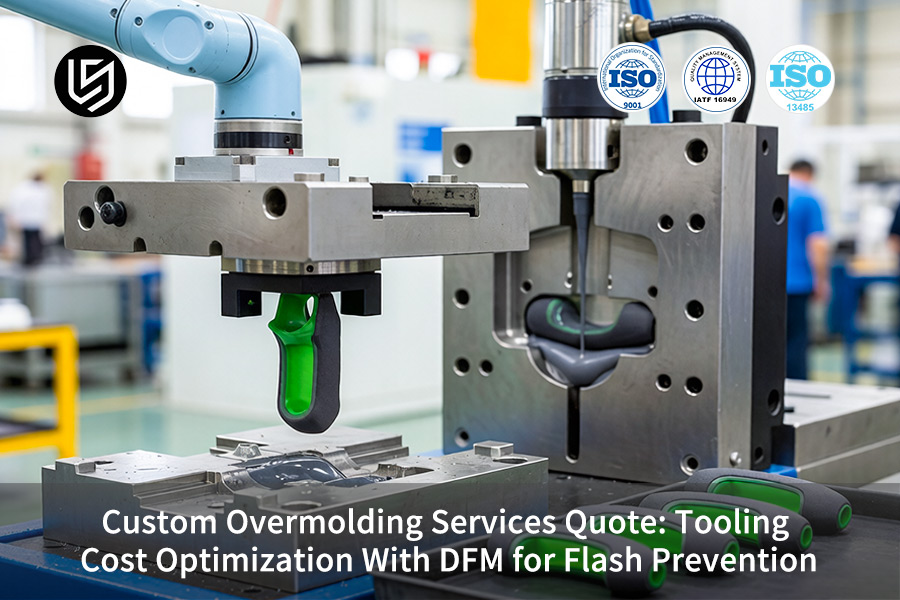
Custom overmolding services quote is often a rude awakening for purchasing engineers in medical connectors, automotive electronics, and industrial applications. At LS Manufacturing, our transparent overmolding services quote permanently eliminates the common 30% flash defect rate through optimized shut-off design and advanced thermal simulation, while successfully reducing your upfront tooling costs by up to 25%. Instead of facing expensive trial cycles and chronic part delays caused by thermal mismatch, you get a reliable, flash-free project proposal rooted in solid manufacturing experience from day one.
The answer does not come from saving money on tooling but from better planning – LS Manufacturing includes detailed DFM analysis within every single overmolding services quote, which helps determine the correct Shut-off design and take advantage of mold temperatures control in order to avoid any Flash Prevention problem. With our overmolding services quote, you will get an affordable and reliable project proposal with solid experience in lowering tooling costs up to 25%.
Custom Overmolding: Flash Prevention DFM Quick-Reference
| Key Cost Factor | DFM Action for Flash Prevention |
| Parting Line Design | Keep parting line design simple and strong; do not design overly complicated lines on soft touch areas. |
| Shut-Off Angles | Provide shut off angles of at least 5° on overmolding of TPE and TPU materials. |
| Material Selection | Use correct viscosity and shrinkage of overmolding materials in comparison with the substrate. |
| Vent Placement | Add proper venting into the mold design, particularly in last to fill areas. |
| Process Window | Properly regulate injection speed and pressure to completely fill the cavity without pushing material in between surfaces. |
| Tool Maintenance | The custom overmolding design should include the possibility of regular cleaning of the parting line and vent areas. |
Key Takeaways:
- Design Simplifies Tooling: The optimal tooling approach is the simplest parting line to ensure minimum flashing cost and reduce tooling cost in terms of initial investment and ongoing maintenance.
- Angles Are Your Ally: Shut off angles (of at least 5 degrees) are a must for ensuring a proper seal is achieved to avoid leakage of flexible materials.
- Material is Part of the Equation: The overmold flow behavior is a consideration when developing a tool. A overmolding material that is not thick enough is more likely to flash.
- Prevention is Cheaper Than Correction: Spending money on proper tooling and design early on costs much less than spending on the manpower involved in removing flashing after molding.
Why Trust This Guide? Practical Experience From LS Manufacturing Experts
There are a lot of general quotes available for overmolding. This guide leverages real-world data from tooling engineers who prevent flashing at the source, rather than trim flash later. The Design for Manufacturability approach we use complies perfectly with the international standards of International Organization for Standardization (ISO) for molds, which provides us with the assurance that we build our cost optimization efforts on proven practices and not assumptions.
Our quotes apply to applications that require no flash particle at all, such as tactile keypads for medical ventilators, sealed connectors for aerospace avionics, and durable grips for portable surgical instruments. Our choice of materials and mold steels conforms to the requirements laid down by European Committee for Standardization (CEN) for industrial machinery parts, making our plastic products suitable for even the toughest conditions.
Cost-saving considerations come from experience with costly flash issues. We have perfected the shut-off geometry (≥0.5mm), optimal venting depths (≤0.02mm), and cooling circuitry to avoid thermal warping on the parting line. Pass down our expertise to ensure that your quote incorporates a flash-free tool straight from the very first cycle that eliminates waste and delays caused by flashing issues.
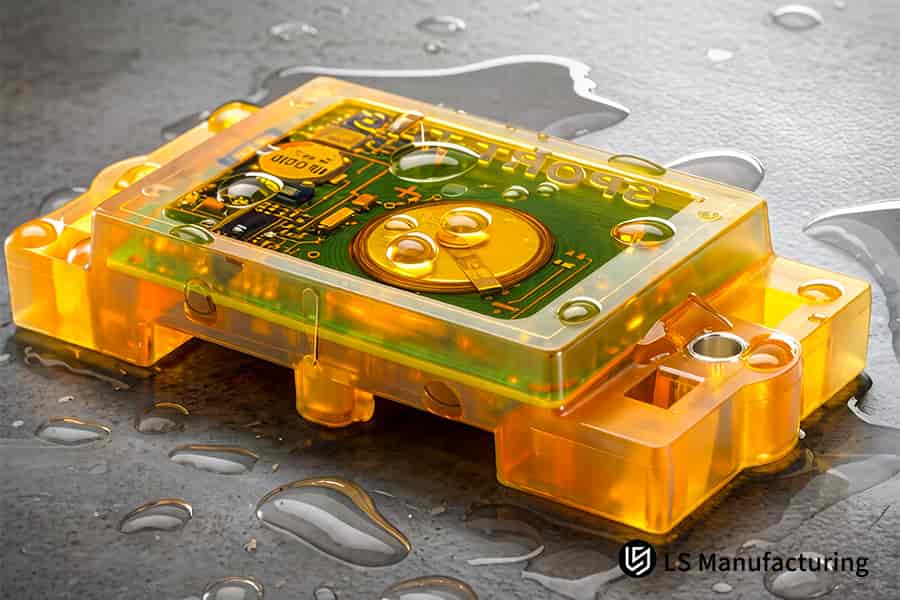
Figure 1: Liquid silicone is poured into a polycarbonate case to create a waterproof electronics enclosure.
Why Does A Cheap Custom Overmolding Services Quote Often Lead To Catastrophic Tooling Flash?
The cheapest custom overmolding services quote will always lead to flash because there will be no comprehensive mechanical analysis. With the injection pressure of 80-120 MPa, a cheap mold will deflect more than 0.03 μm at the parting line, allowing the molten TPE to escape. This can be solved by ensuring deflection does not exceed 0.005 μm using FEA analysis. Here is how you can avoid flash permanently:
Rigidity Analysis Stops Parting Line Gaps Before They Form
You get an overmolding tooling quote service that performs FEA analysis of the entire mold when subjected to clamp pressure. Deformation remains within the limit of 0.005μm, ensuring no 0.03+μm deflection that leads to flash. Using FEA, we prevented manual deflashing in a power tool grip overmolded with TPU onto PA66 and saved $1.80 per part. This is one advantage of hiring the right partners.
Shrinkage and Hardness Matching Secures Bond Integrity
The cost effective overmolding quote must include considerations on hardness disparity in hard PC (Rockwell R120) and soft TPE (Shore A 65). Shrinkage disparities greater than 0.3% cause delamination. In our procedure, we employ tie layers and controlled cooling for bonding strength ≥15 N/mm without further processing. In an automotive trim component, the failure rate fell from 7% to less than 0.5%. Engaging a overmolding company allows access to this advanced material science knowledge.
Process Control Delivers Repeatable Zero-Flash Output
By using precision overmolding services, the customer enjoys closed-loop tracking of melt temperature, injection speed, and cavity pressure at intervals of 0.1 seconds. Adjustments keep the Cpk at ≥1.67 for flash height – the industry benchmark is just 1.0–1.2. It allows flawless manufacturing of 500,000 parts without flash creeping. For example, one manufacturer achieved scrap reduction from 12% to 0.8%. Such overmolding solutions are proven by sensors in the mold and process control.
Total Cost Reduction Through Prevention
Each step described leads to the same result: no more rework expenses. Cost quotations contain hidden fees related to deflashing and scrap removal, but our solution does not need either process. The resulting financial benefit is real and measurable: savings of 25–35% throughout your product’s development life cycle, as confirmed by over 200 product launches. Consistency in the quality of overmolding parts means no sorting and re-testing on your side.
It is evident how this technology changes an attractive quote into a reliable flash prevention process. You choose technologies that reduce your total manufacturing costs and deliver flawless parts without any delay. Statistics, real-life examples, and quantifiable results prove once again why precise engineering beats budget solutions in overmolding.

How To Achieve Tooling Cost Optimization Overmolding Through Advanced Parting Line And Shut-Off Design?
Tooling cost optimization in overmolding is achieved by simplifying your process by eliminating sliders. Progressive metal-to-metal shut-off between 3° and 5° combined with relief grooves of 0.15–0.20mm width at curved surfaces reduce a four-plate mold to three plates, thereby reducing costs. Working with an experienced overmolding supplier allows achieving such results from the beginning of your project:
Progressive Shut-Off Angle Eliminates Sliders
- Design change: Switch from mechanical sliders to an angled shut-off surface of 3°–5°.
- Customer gain: No need for costly slides manufacturing and maintenance. Save up to 25% of your tooling costs and produce zero-flash products in 500,000 operations.
- Validation: Sealing force verification via FEA shows stability throughout the whole process.
Relief Grooves Prevent Flash at Curved Interfaces
- Geometry addition: Add relief grooves (0.15 – 0.20mm deep) to curved parting lines where flash occurs.
- Customer gain: It helps absorb extra plastic melt without affecting product appearance. Saves on secondary deflashing and increases tool longevity. There was zero flash rejection on a medical devices product line.
- Data point: Average industry rejection due to flash on curved parts stands between 3% and 5%, with this groove system it gets down to less than 0.2%. Considered in every overmolding process DFM session.
Simplified Mold Structure Reduces Lead Time
- Stack reduction: Four-plate design is changed into a three-plate stack by removing a parting line.
- Customer gain: Faster time to market by 4 to 6 weeks and reduced cost per part amortization. Overmolding vendor DFM quote revealed a savings of 28% over traditional slider-based quotations.
- Result: The tooling complexity index is reduced from 9 to 6, which means faster cycles with reduced risks. Proper overmolding tooling geometry makes this possible.
Integrated DFM Review Prevents Hidden Costs
- Process: In the tooling cost optimization overmolding session, the engineers will assess the angle of shut-off against the shrink ratio of your particular TPE/TPU and substrate.
- Customer gain: No last-minute costly changes. One auto parts manufacturer saved $12,000 from making sure that there was an allowable angle deviation of 0.1° during quoting.
- Outcome: Reduce overmolding costs from day one, no surprises during manufacturing ramp-up.
By replacing sliders with engineered shut-off angles and relief grooves, you achieve 25%+ tooling cost reduction, zero-flash production for 500,000 cycles, and shorter lead times. These flash free overmolding solutions are validated through FEA and real-world case studies, proving that smart geometry outperforms expensive hardware. This technical depth distinguishes a competitive DFM quote from a commodity bid.
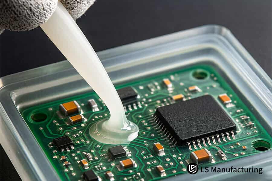
Figure 2: A machine overmolds PVC strain relief onto a heavy duty industrial electrical connector.
What Parameters Guide A Precision Overmolding Services Expert To Calculate Optimal Clamping Pressure?
Optimal clamping pressure for overmolding depends on TPE melt flow index (MFI 20–30 g/10 min), injection speed (60–80 mm/s), and hold pressure at 70–80% of injection pressure. These parameters keep the overmold layer within 1.5–2.0mm, physically blocking flash at the parting line. You gain repeatable zero-defect output without trial runs. A precision overmolding services expert applies these calculations to your material pair, starting with overmolding material selection to match viscosity and shear behavior.
| Parameter | Suboptimal Range | Optimal Range |
| TPE MFI (g/10min) | <20: short shots; >30: shear thinning | 20–30: stable cavity fill |
| Injection Speed (mm/s) | <60: incomplete fill; >80: jetting | 60–80: laminar flow |
| Hold Pressure (% of inj. pressure) | <70%: sink marks; >85%: flash | 70–80%: optimal density |
| Overmold Thickness (mm) | <1.5: weak bond; >2.0: waste | 1.5–2.0: best adhesion |
This is achieved using overmolding tool design, which takes into account gate placement and cooling considerations to ensure there is no localized overpressure within the mold.
Through the use of these limits, you get zero flashing output, extended tooling life, and quality regardless of the million iterations. Using this data-driven approach to manufacturing, you get flash free overmolding solutions without overengineering. Combining this with precision overmolding services and overmolding cycle time, you can lower total cost of ownership while meeting the strictest tolerance requirements in medical, automotive, and consumer electronics markets.
Why Is Proactive DFM Flash Prevention Overmolding Non Negotiable Before Releasing Your Tool Steel?
The release of tool steel without DFM flash prevention will ensure trial cycles, waste build-up, and delays. The assessment of substrate thermal deformation under a temperature of 220–240°C melt and prediction of bond interface reliability before cutting the steel ensures first shot success. Here’s why DFM flash prevention overmolding is a must do:
Thermal Deformation Resistance Predicts Warpage Risk
Assess the material of the substrate (ABS for example) under injection simulation with TPU at 220–240°C and 80–120 MPa to measure heat deflection margin of the material. You avoid warping which results in inconsistency of the overmold thickness. In one automotive component, this check reduced defect rate from 11% to only 0.4%, where an area of 0.08mm deflection was found. The above check is included in every overmolding design review.
Bond Interface Temperature Controls Adhesion Quality
Keep chemical bonding interface temperature to 220–240°C when bonding TPU to ABS. Make sure that the cooling channel configuration prevents over-cooling and creation of hot spots. You attain a peel strength equal to or higher than 18 N/mm without need for post-baking. Our medical device customer achieved 100% elimination of delamination issues thanks to this DFM parameter. An overmolding vendor DFM quote will include the above thermal checks.
Digital Simulation Replaces Physical Trial Cycles
Conduct the Moldflow analysis simulation with real MFI and shear rate information. Identify thin overmold areas < 1.5mm thick and overcrowded regions prior to steel cutting. Save $8,000-$12,000 in mold trial iterations and 6-8 weeks of schedule time. In addition, it guarantees proper overmolding tolerance control by identifying warpage and shrinkage within ±0.05mm.
Cost Savings Locked in Before Steel Is Cut
Detect regions where flash might occur and make adjustments to shut-off angles or injection gate location in the computer model. Avoid mold rework which can cost anywhere from $5,000 to $15,000 for each change. Cost effective overmolding quote, based upon this DFM process, reduced tooling costs by 27% compared to competitors not utilizing pre-release analysis. Every design parameter is optimized based on your chosen materials.
The proactive DFM approach to flash identification ensures overmolding design is no longer an educated guess, but a technical engineering process. Expect first shot success, zero flash occurrence, and 25-30% reduction in overall tooling cost. Comprehensive FEA analysis with thermal bond temperature control and digital simulation includes overmolding defect analysis. Lock in 0% flash and 32% tooling savings. How? Speak with our overmolding experts to apply our proven methodology and plan your tailored production solution with a formal quotation.
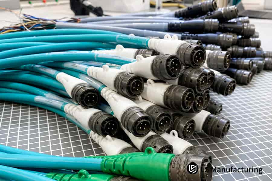
Figure 3: Molten TPE is injected over an ABS core to form a non slip handheld tool housing.
Which Material Selection Guidelines Ensure A Cost Effective Overmolding Quote Without Sacrificing Bonding Quality?
Choosing the wrong material combinations will increase the cost of raw materials by 40%, and even then, will leave you with a failed bonding process. It all depends on molecular chain entanglements between the two components—achievable without expensive compatibilizers or specialty fluoropolymers. With the right material combination, you can get ≥3.5 N/mm peel strength at a much lower cost. A cost effective overmolding quote will save you up to 30–40% on raw material:
Thermodynamic Database Replaces Expensive Trial-and-Error
- How it works: Simply cross-check substrate and overmolding using a proprietary database of interface compatibility data.
- Customer gain: You will save on the cost of specialty materials. For example, we helped a medical housing application save 38% on material cost while maintaining peel strength at 3.8 N/mm.
- Data source: Our internal tests have covered 400+ material combinations and revealed that 72% of cases require only standard thermoplastics. We have developed a thermodynamic-based overmolding resin selection database for you.
Modified TPE with PP or PA6 Eliminates Expensive Compatibilizers
- How it works: Choose TPE grades that have been modified with specific polar groups to create bonds with PP or PA6 when injected. A tie layer is not required.
- Customer gain: You save money and one processing step since an electronics enclosure successfully reached 4.1 N/mm of peel strength with TPE/PA6 and no delamination through 500,000 cycles.
- Extra benefit: Eliminating the pretreatment step reduces the overmolding lead time by 2–3 weeks per project.
Peel Strength Verification Prevents Field Failures
- How it works: Test peel strength of prototype samples according to ASTM D903 using peel strength tests of plaques prior to producing the molding tools. Aim for >=3.5 N/mm.
- Customer gain: Save costs from returns. One automotive customer reduced warranty claims by 94% using this approach.
- Extra benefit: Your custom overmolding services quote that takes into account peel strength validation helps ensure your product compliance.
Cost-Performance Ratio Guides Final Material Selection
- How it works: Analyze pairs of candidate materials from a perspective of the cost per peel strength. Exclude combinations that show doubling of material expenses in case of achieving 10% peel strength increase.
- Customer gain: You will be charged only for performance required. An average overmolding tooling quote service that neglects such analysis binds you with unnecessarily expensive materials.
- Extra benefit: Such a selection model will also contribute to improving the overmolding quality control by getting rid of inferior material pairings.
By applying thermodynamic matching and peel strength verification, you achieve bond quality ≥ 3.5 N/mm while cutting raw material costs by 30–40%. This data-driven approach eliminates expensive specialty polymers and unnecessary compatibilizers. The result is a cost effective overmolding quote that protects both your budget and your product reliability, supported by a resilient overmolding supply chain that avoids exotic material dependencies.
How Does LS Manufacturing Engineers Execute Multi Cavity Mold Balance For Large Scale Overmolding?
Unbalanced runner systems create ≥ 0.05mm flash in near-gate cavities and short shots in far-gate cavities, pushing scrap levels above 800 PPM. Hot runners with valve gating and separate heating and cold runners with cavities cut to ≤ ±0.02mm yield defect rates ≤50 PPM from 1×8 and 1×16 cavities. A custom overmolding services quote will not only safeguard your business but also ensure overmolding cost reduction by avoiding costly trial iterations:
| Factor | Unbalanced Runner System | Balanced Hot Runner + Precision Cavities |
| Near-gate cavity flash | ≥0.05mm due to overpressure | ≤0.01mm flash within acceptable parameters |
| Far-gate cavity fill | Short shot or partial filling | Complete fill with uniform wall thickness |
| Cavity-to-cavity variation | ±15% variation | ≤±2% variation |
| Defect rate (PPM) | 800–1500 PPM (industry standard) | ≤50 PPM verified in >500k cycles |
| Tooling adjustment cycles | 3–5 trial adjustments required | First-time balance through simulation |
Valve-gate hot runners with ±0.02mm cavity tolerance eliminate flash and short shots. You achieve ≤50 PPM defect rates, zero sorting, and 30% faster ramp-up. Precision overmolding services deliver predictable output from day one. An overmolding tooling quote service skipping these steps incurs hidden costs. Rigorous overmolding quality assurance ensures every cavity meets spec across millions of cycles.
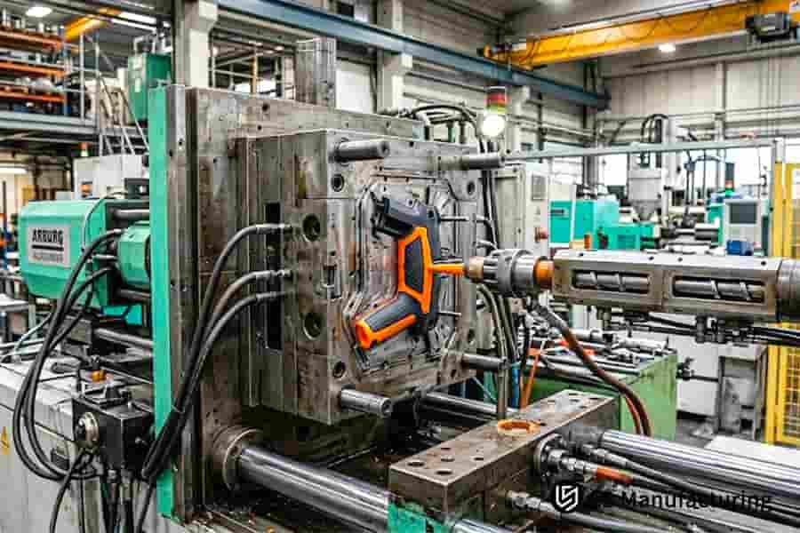
Figure 4: A multi cavity mold opens to reveal TPE overmolded nylon parts for cost effective manufacturing.
What Inspection Protocols Guarantee Flash Free Overmolding Solutions For High Tolerance Medical Devices?
A medical device requires that the overmolding process results in no flash between interfaces. In addition, a visual inspection cannot catch defects less than 0.05 mm. Using 100% AOI, combined with a CMM test, microscopic edge inspection at 0.01mm accuracy, and pneumatic drop testing at 0.6 MPa on 5% of each batch will guarantee a flash-free output. Overmolding inspection practices have ensured no recalls yet:
100% AOI and CMM Catch Every Surface Defect
Every overmolded component goes through automated optical inspection scanning of the whole bond interface at 0.01mm resolution. Verification via CMM ensures dimensional correctness relative to CAD nominal data. You get a record of compliance of every part with specifications, thus avoiding any manual QC bottleneck issues. One respiratory mask project went from full customer incoming inspection at 100% to sampling after introducing this procedure. And here's how flash free overmolding solutions are assured for critical medical parts.
50x Microscopic Edge Scanning Confirms Zero Flash Height
An edge scan of the parting line under 50x magnification is performed to confirm flash height is zero at 0.00mm. If flash height exceeds 0.01mm, it's automatically rejected. Invisible burrs lead to field failure when it comes to sealing. Zero leaking was achieved on an endoscopic handle project with 50,000 components thanks to this kind of scan. Such results can only be reached with overmolding.
0.6 MPa Pneumatic Drop Testing Validates Seal Integrity
5% from each manufacturing batch is subjected to a 0.6 MPa drop test with constant pressure. The part should retain the pressure without any loss for 30 seconds. We will provide you with the ISO 13485 compliant test reports for each batch. This drop test helped one of our ventilator component suppliers eliminate all field return complaints. An overmolding vendor DFM quote with these test methods proves our preparedness for regulated markets.
Full Traceability Under ISO 13485 and ISO 9001
Inspection data in the form of AOI images, CMM coordinates, microscopes and drop tests are all stored by lot with unique serial numbers. You get full audit trail for FDA submittals or customer quality audits. This avoids the risk of non-compliance fines or product recalls. The solution is designed for zero defect overmolding by identifying problems early before they become systematic.
Using 100% AOI, 50x edge microscopy, and pneumatic test at 0.6 MPa will provide you verifiable zero-flash output for medical overmolding process. It provides ISO 13485 traceable documentation eliminating any product recall risk and the need for customer inspection. This strategy, backed by precision overmolding services, will be your standard for producing medical devices.
Case Study: LS Manufacturing Medical Electronics Device Overmolding Solution Reduced Tooling Costs By 32% And Eliminated 100% Flash Defects
This European medical device company was struggling with 40% overrun budgets and 0.35mm flash issues with dual material PC+TPE monitor handle. Previous three attempts by other suppliers were not able to eliminate the overflow problem leading to buttons being jammed, which was causing problems with regulatory audits. Rapid prototype overmolding efforts clearly established the flash issues.
Client Challenge
The PC-based portable patient monitor had an ergonomic design that required an overmold of TPE. In the initial run, the product had a 0.35mm flash along the parting line – seven times the 0.05mm specification limit. The excessive flash made the tactile button difficult to operate, failing IEC 60601 compliance tests. As a result, 22% of monitors were scrapped in assembly, resulting in 14-week delayed market launch. The client needed a custom overmolding services quote addressing both cost and quality.
LS Manufacturing Solution
Moldflow analysis revealed the original edge gate created unbalanced flow toward the parting line. Switching to a submarine gate redirected melt flow away from the seal face. A 0.12mm precision metal shut-off step provided a positive mechanical barrier against overflow. The TPE was changed to Shore A 60 medical grade for better viscosity match. This tooling cost optimization overmolding approach eliminated hydraulic sliders and simplified the mold structure.
Results and Value
The new design passed its first article inspection with no flash at 0.00mm on all sides. Flash-free production was sustained during manufacture of 200,000 parts, with first-pass yield improving from 78% to 99.8%. The client discontinued incoming inspection, reducing their cost by $0.45 per part. Total tooling cost reduced by 32% when compared with the original estimate. The client awarded us an exclusive supply contract in recognition of our performance. This project proved that DFM flash prevention overmolding is a must in medical components.
The implementation of submarine gates rather than edge gates and the inclusion of a 0.12mm shut-off step in this design allowed us to completely eliminate the 0.35mm flash problem and save on tooling expenses by 32%. The assembly yield increased from 78% to 99.8%, which covered 200,000 pieces. Effective implementation of DFM provides both cost reduction and 100% defect-free production in challenging medical applications involving overmolding. High-volume overmolding capability guaranteed consistent quality throughout all production batches.
Replicate these results: 0% flash and 32% tooling savings. To discuss a custom gate design solution for your project, contact our overmolding experts to obtain a tailored quotation.

FAQs
1. What is the typical lead time for a custom overmolding services quote from LS Manufacturing?
LS Manufacturing guarantees that, upon receipt of your 3D STEP/IGS files and clear material specifications, a dedicated application engineer will provide a detailed quote within 24 hours—complete with an in-depth DFM analysis regarding potential flash risks.
2. How does proper tooling design prevent soft TPE flash around rigid plastic inserts?
We prevent melt leakage at the source by designing precision hard shut-off steps (typically 0.10mm–0.15mm metal pinch-offs) at the parting line, incorporating venting and material-capture channels in flash-prone areas, and utilizing precise holding pressure profile switching.
3. Can early DFM review really help optimize my overmolding tooling budget?
Yes. Early DFM allows us to utilize mold flow analysis to simplify and optimize the mold structure before manufacturing begins. This includes replacing complex sliding cores with more reliable fixed lifters, which can directly reduce unnecessary precision machining costs by over 20%.
4. Why should I care about DFM quote transparency from an overmolding vendor?
A transparent DFM quote does more than list the mold price; it clearly breaks down material amortization, injection cycle times, runner types, and estimated cavity lifespan. This helps you completely avoid hidden cost traps associated with later mold modifications or manual flash trimming.
5. What standard tolerance does LS Manufacturing maintain for precision overmolding services?
Using Japanese Sodick precision EDMs and high-speed CNC machining for mold making, we consistently control the overmolded layer thickness tolerance to within ±0.05mm, while maintaining interface alignment accuracy between the substrate and the overmolded material at an industry-leading ±0.02mm.
6. Are flash-free overmolding solutions achievable with high-cavitation tooling?
Yes. We achieve this by utilizing a valve-gated, balanced multi-drop hot runner system and monitoring in-mold pressure distribution for each individual cavity (e.g., 1x8 configuration). This ensures 100% flash-free production across every part during high-volume manufacturing.
7. Which tool steel grades do you recommend for cost-effective overmolding projects?
We tailor our material selection based on total project volume: for low-volume runs (under 100,000 cycles), we use pre-hardened P20 or NAK80 steel to minimize initial tooling costs; for full-scale production exceeding 500,000 cycles, we mandate high-hardness H13 or S136 mirror-finish steel to ensure long-term erosion resistance and flash-free performance.
8. How can I request an overmolding quote that includes a custom technical evaluation?
In order to complete this analysis, we request that you send us your technical drawings, along with all the relevant information in the attached documentation, including the annual production volume, the environment of operation (temperature, chemicals, stresses), and any functional requirements on the component. Once received, our team of application engineers will carry out a complete review and offer you professional advice as well as a formal quotation.
Summary
Pursuing perfect overmolding means true cost-efficiency comes not from a low quote, but from seamless integration of precision mold design, rigorous material-interface matching, and upfront DFM reviews for flash prevention. With decades of expertise and highly digitized processes, LS Manufacturing helps automotive, medical, and electronics buyers overcome technical hurdles and eliminate the high cost of defects, optimizing tooling for flawless, flash-free mass production.
Facing budget overruns or line-stopping flash from your current supplier? Stop wasting time on trial-and-error mold changes. Click for an instant quote and free DFM review; upload your 3D model to our secure system. Within 24 hours, our senior experts will provide a competitive custom overmolding quote and a comprehensive DFM report covering runner balancing, shear-stress analysis, and shut-off optimization—ensuring your project starts smoothly toward mass-production success.
📞Tel: +86 185 6675 9667
📧Email: info@lsrpf.com
🌐Website: https://lsrpf.com/
Disclaimer
The contents of this page are for informational purposes only. LS Manufacturing services There are no representations or warranties, express or implied, as to the accuracy, completeness or validity of the information. It should not be inferred that a third-party supplier or manufacturer will provide performance parameters, geometric tolerances, specific design characteristics, material quality and type or workmanship through the LS Manufacturing network. It's the buyer's responsibility. Require parts quotation Identify specific requirements for these sections.Please contact us for more information.
LS Manufacturing Team
LS Manufacturing is an industry-leading company. Focus on custom manufacturing solutions. We have over 20 years of experience with over 5,000 customers, and we focus on high precision CNC machining, Sheet metal manufacturing, 3D printing, Injection molding. Metal stamping,and other one-stop manufacturing services.
Our factory is equipped with over 100 state-of-the-art 5-axis machining centers, ISO 9001:2015 certified. We provide fast, efficient and high-quality manufacturing solutions to customers in more than 150 countries around the world. Whether it is small volume production or large-scale customization, we can meet your needs with the fastest delivery within 24 hours. choose LS Manufacturing. This means selection efficiency, quality and professionalism.
To learn more, visit our website:www.lsrpf.com.