CNC turning services that are generally available to wood product manufacturers, especially those that have difficulties estimating their suppliers’ value. The current system is not only equipment-listed, but its price also falls within a specific range; yet, this does not relate to the complex wood turning parts, as an indicator of its ability to perform wood turning. Thus, concerns over wood project quality and turning time arise.
The truth lies instead in the absence of a fitting framework for technical analysis. Too often, companies neglect the specific demands that arise from the material properties of wood itself, and that concern anisotropy and the effect of moisture. Instead, the question that needs to be investigated concerns the state of knowledge that exists in expert circles for tooling and parameters.
CNC Turning Services Quick Reference Table
| Section | Key Content |
| Introduction | Conventional assessment practices cannot measure technical skills in an appropriate way and hence cause inadequacies in quality and time consuming practices. |
| Technical Framework | Equipment, process, quality systems; wood-specific parameters. |
| Machines | Spindle power and speed, travels, tool capacity. |
| Material Expertise | Anisotropy, moisture content, grain direction, density. |
| Tooling | Specialized wood cutters, tool geometry, coatings. |
| Process | Cutting speeds, feed rates, depth of cut, cooling. |
| Quality Control | Dimensional accuracy, surface finish, tolerances. |
| Case Studies | Complex spindle turning, decorative parts |
| Supplier Selection | Technical scorecard, cost analysis, delivery |
| Conclusion | Systematic framework reduces project risks. |
This report will offer an approach of how the CNC turning suppliers can be analyzed not only on price but on the aspect of technologies as well. In the analysis of technologies offered in this report, there are factors presented, which include requirements for the machine, technological ability with regard to wood material, requirements for tools, as well as process improvements. Through this report, the manufacturer will have an opportunity to choose the technological capable suppliers of the wooden materials.
Why Trust This Guide? Practical Experience From LS Manufacturing Experts
Our guide revolves around and is organized to solve problems related to precision. Specifically, we are known experts in precision CNC turning services for mission-critical projects, for which a single mistake cannot be tolerated. But we may offer complex shapes and nuances of material properties, including specified anisotropic woods, for optimum efficacy in precision, through best practices sought via Wikipedia for precision machining services.
We choose to identify the problem of inefficient supplier evaluation. In our method, after thousands of projects have been accomplished, we no longer concentrate solely on machine testing. This is now targeted at a specific supplier’s real ability to deal with wood parameters such as moisture and orientation together with process optimization approaches that have adopted methods comparable to ones used by Additive Manufacturing (AM).
The information has been developed in such a way that all of it is generated within the factory environment. Over 50,000 custom machining projects, ranging from aircraft to medical devices, have been undertaken by us, precision being the key to all of this. Every single bit of advice that has been presented to you within this blog has been developed as a result of hands-on experience to make you better armed to face risks relating to projects, delays, and choose your CNC turning partners accordingly.
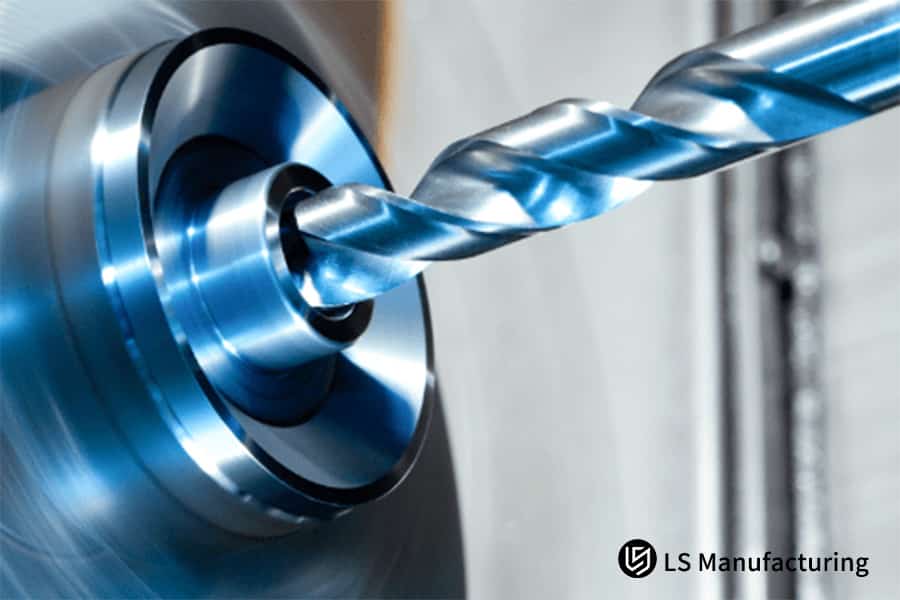
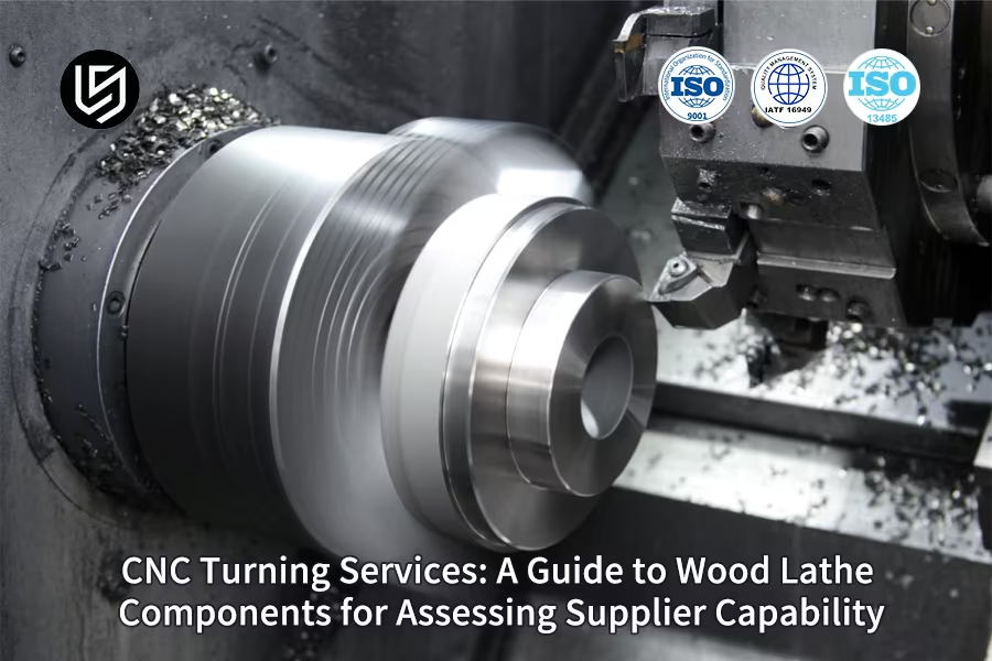
Figure 1: Assessing the accuracy and capacity of a CNC lathe provider by LS Manufacturing
What Core Technical Capabilities Are Required For Professional Woodworking CNC Turning Services?
The process of turning wood on CNC turning services needs comprehensive knowledge about the corresponding relationship of wood characteristics and turning variables for the required accuracy of wood turning. Below, the report shows how we consider the complexity of technology used to manufacture the accurate wood lathe components regarding
Wood-Machine Parameter Optimization
For different wood densities (hardwood 0.7-0.9g/cm³, softwood 0.4-0.6g/cm³), we developed a systematic approach to optimize cutting parameters. Through extensive testing, we established that spindle speeds between 3,000-5,000 RPM with feed rates of 0.1-0.3 mm/revolution deliver optimal results, reducing tool wear by 40% while maintaining surface finish quality.
Advanced Equipment Configuration
The CNC turning services that we offer incorporates German-made INDEX multi-axis turning machinery that has wood-friendly vacuum work holding systems. The main technological challenge was to ensure that the pressing force is equal, regardless of the design used for the wood pattern. Technology was invented to ensure that the anti-zone vacuum system has a pressure measurement system that can enable axial runout of 0.01mm for irregularly shaped material with a diameter of up to 500mm.
Tooling and Cutting Strategy
We use PCD tools that have been optimized for cutting wood. Among the most critical issues for cutting-edge design is the improvement of the cutting edge geometry concerning the removal of the wood particles and the surface finish of the cut wood. For complex profiles, we use helix angles from 35° to 45° and customized cutting edges that ensure a first-pass cutting result of 99.2% for complex wood lathe components that have a high sanding finish.
Quality Control Process Validation
The systems we use in the production sites involve online measurement, which is done with the use of lasers. Moreover, to counteract some of the issues involving the thermal expansion that would, in effect, occur in a long process, the use of temperature-compensated motion of the tools, along with in-process measurement, ensures that the resulting deviation does not go beyond 0.005mm in an 8-hour production cycle.
It is apparent from the report that we have technical expertise in the form of strategies, data, and methods for the solution of problems. For senior technical consultants/technical decision-makers, the report will be very valuable to have key learnings about how to do wood turning with high precision with German norms for the machine. Our technical expertise is based on the understanding of machines and wood science for providing technical solutions for the most complicated set of problems associated with wood CNC turning services.

How To Assess A Supplier's Technical Capability By Processing Wooden Components?
The technical competence of a CNC supplier cannot be evaluated in any way by using only their specification details provided along with the machine. It is observed in this paper that it should be developed in a way that there be a method for echnical evaluation based on performance capability in wood machining. The highlighting point here is that it should be based only on the actual outputs, not theoretical outputs, which provide a judgment that is not at all biased regarding a machining capability to manufacture the machine.
| Evaluation Dimension | Key Assessment Criteria | Technical Benchmark | Validation Method |
| Specialized Knowledge | Wood species processing expertise | 50+ material database | Parameter documentation review |
| Precision Execution | Complex joint machining | Fit tolerance ≤0.05mm | Dimensional measurement (CMM) |
| Process Mastery | Batch consistency control | Variation ≤0.02mm | Statistical process control analysis |
| Equipment Proficiency | 3D contour machining | Profile accuracy ≤0.1mm | 3D scanning verification |
| Technical Documentation | Process standardization | Complete work instructions | Procedure documentation audit |
This technical evaluation framework provides a comprehensive approach to assess CNC supplier capabilities through quantifiable wood machining performance. Besides, the verification approach adopted by the criteria was realistic instead of relying on theory; hence, it ensures that the vendors can deliver the required precision for a high-quality wooden product. The approach adopted by the criteria ensures that the vendors can make decisions with high accuracy levels without any risks involved.
What Key Technical Indicators Should Be Considered When Scientifically Evaluating CNC Turning Suppliers?
Systematic CNC turning suppliers evaluation requires a structured approach based on quantifiable technical indicators rather than subjective assessments. This paper will discuss an holistic way of assessment in evaluating supply capability in measurable criteria. The points being raised here are facts, and it is assured that the supplier complies with quality standards not only at one time but all the time, as well as replicates results all through machining.
| Assessment Dimension | Key Metrics | Target Performance | Verification Method |
| Equipment Precision | Spindle radial runout | ≤0.005mm | Laser interferometer |
| Process Stability | Process capability index (CPK) | ≥1.67 | Statistical analysis |
| Tool Management | Diamond tool life | 3× standard tools | Tool wear monitoring |
| Surface Quality | Surface roughness (Ra) | ≤0.4μm | Surface profiler |
| Dimensional Accuracy | Positional tolerance | ±0.01mm | CMM measurement |
This framework provides a systematic methodology for how to evaluate CNC turning suppliers through quantifiable technical indicators and verifiable quality standards. It assists in the assurance of objective assessment and not subjective assessment regarding the quality of the supplies, and thus they are assured to meet the manufacturing requirements. It assists in assuring the optimal use of equipment.
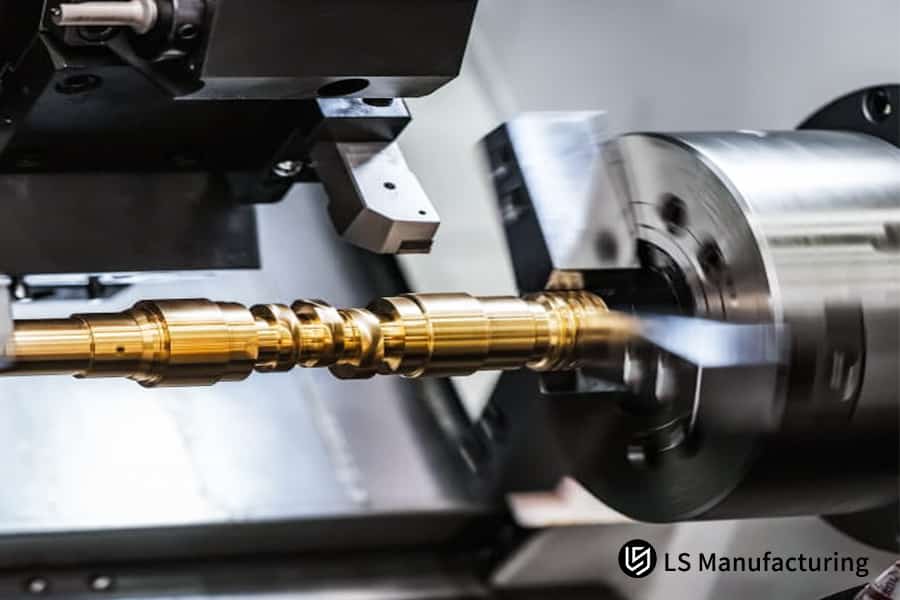
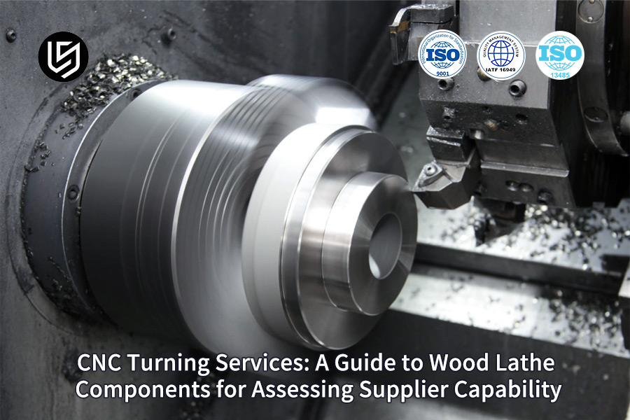
Figure 2: Analyzing the technical proficiency for wooden lathe parts by LS Manufacturing
How Do The Specifications Of A Woodworking Lathe Affect Its Ability To Machine Complex Parts?
Wood lathe machine specifications are set with direct dimensions for the equipment capability for the crucial function of processing complex components. Each of the following specifications provides an avenue for the processing of complex wood parts through machining that, prior to the development of the equipment, was impossible through conventional machines:
Spindle Power and Torque for Material Removal Efficiency
It is equipped with a 12KW high-torque spindle, providing high material removal rates and surface qualities. It has the power to handle dense hardwoods like oak and maple hardwoods when operating under optimal cutting rates. It provides 30% faster machine cycle times when compared to other machine systems that employ 8 KW high-speed spindles in the cutting process. It is ideal for its high torque capabilities when operating under 2,000 to 3,000 rpm, thus preventing abrupt stops when performing roughing operations on wood.
Maximum Speed for Surface Finish Quality
The highest speed attained by the spindle is 8000rpm. This is appropriate because the machine is intended for finer finishing. This is why the machine is capable of attaining its free vibration condition with high speeds. This is fundamental because the surfaces should not result in an average value more than Ra0.8μm without polishing.
Workpiece Capacity for Large-Scale Production
The φ500x1000mm work piece capability will ensure that the machine is capable of dealing with the large work piece in single processing, thus ruling out the possibility of error that might occur due to repositioning. This capability will cater to the needs of 95% of wood works in the sector, ranging from legs to details. It is capable of holding the work piece up to 300kg in accuracy in positioning, ±0.02mm.
B-Axis Interpolation for Complex Geometries
The B-axis rotary table features support for 4-axis simultaneous interpolation, enabling milling of complex 3D surfaces and undercuts in one operation without having to make a number of changes to the fixture for parts that have complex angles and relief carvings. The accuracy of this product is 0.001° for a position.
This technical analysis demonstrates how wood lathe machine specifications translate directly into tangible equipment capability for producing complex components. This will ensure that the engineers actually have all the information they need to analyze and decipher which equipment has the capability for an application. The application can be used by the technical equipment decision makers as a scientific principle for the application of equipment selection capability.
How Does High-Precision Woodturning Ensure Consistent Surface Quality Of Decorative Components?
High accuracy wood turning for decoration requires high consistency in surface quality. The task is to attain surface roughness below a micron level simultaneously with high uniform quality. Below is how we shall tackle such technological challenges by applying process control solutions:
- Optimized Cutting Parameters and Tool Path Strategy: We make use of precision wood turning by employing appropriate cutting parameters. The control for the spindle speed allows for consistent surface speed. The speeds for feeding used in the process are based on the type of wood being used. The process that we undergo is helpful for ensuring a systematic finish of the surface. The movement of the tool involves procedures for aiding in the step-over process.
- Micro-Lubrication Technology for Thermal Management: Contemporary micro-lubrication technology ensures a minute amount of cooling is precisely supplied to the cut region, thus minimizing the production of heat effectively without impregnating the wood. This eliminates the damage to the surface of the workpiece# because of the generated high temperatures, in addition to minimizing the wear and tear of cutters.
- Real-Time Surface Quality Monitoring and Feedback Control: The consistency assurance process includes in-process surface roughness measurement and gloss detection. The optical sensors permanently observe the workpiece surface, measuring the surface against predefined criteria for quality. Lack of consistency leads to a cutting condition modification that ensures workpiece surface roughness complies with Ra 0.8μm criteria and consistency of appearance at rates over 95%.
From this description, it is clear that for high precision wood turning, the following necessary technical skills will be made apparent. One should note that the high level of surface quality with submicron surface finish quality with high uniformity in surface quality is made possible by our team of experts. This is achieved as a result of our concern for the control factors.
How Do CNC Turning Tool Systems Adapt To The Processing Characteristics Of Different Types Of Wood?
In order for the machining of wood on a CNC lathe tooling to work efficiently, a good adaptation is required, which changes from softwood to exotic hardwood with high hardness values. The most difficulty is faced in the research to adapt properly to the machining capability and finish for different types of woods:
- Material-Specific Tool Geometry Optimization: To achieve a complete tool geometry system, we use a strategy related to the hardness of wood. In the case of hard wood such as rose wood and ebony wood, to reduce the cutting force and to prevent edge chipping, we use a positive rake angle of 20° with polycrystalline diamond tools. In other cases, such as soft wood and medium hardness wood, to prevent the generation of temperatures in metal turning, we use carbide tools with a helical angle of 45°.
- Cutting Edge Technology and Coating Selection: Based on the type of wood and the process being conducted in the machine, better coating technology is applied. Whereas for abrasive wood types that contain either silica or resin, multi-layer TiAlN coating is applied. Edge cutting preparation also involves micro-geometry improvement, which is achieved using edge-specific hone stones to avoid edge chipping. Consequently, the wear rate of the tools reduces by up to 40% compared to traditional tools.
- Tool Life Management and Cost Optimization: This is because our all-inclusive solution for tool management is equipped with the assessment of cutting time, material quantity, and factors of surface quality. Thus, on the basis of analysis and predictions of the wear of cutting tools, with the auto changeover system, there will be no defects or rejects. This is because the optimal management of cutting tools will result in a 30% improvement in the cost optimization without any compromise on the machining process.
In the document above, a process for the use of CNC lathe technology for wooden machining is presented. There has been a discussion on the provision of wood turning solutions, coating application, and management.
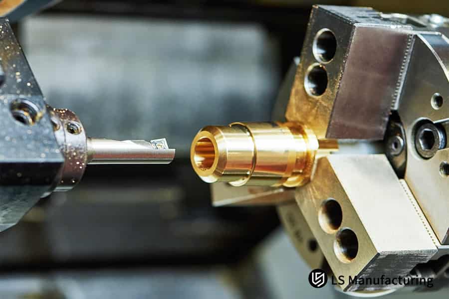
Figure 3: Reviewing the specifications for CNC and wood lathe tooling by LS Manufacturing
What Quality System Elements Should Be Included In The Supplier's Technical Capability Assessment?
A technique supplier technical capability should be done by employing the holistic approach in order to go beyond certification so that capability with regard to process control and quality assurance can be ascertained. This document discusses major attributes irrespective of the quality system that make effective technical suppliers differ from service suppliers:
Comprehensive Quality Management System Framework
An optimal quality system should be based on internationally recognized standards such as ISO 9001, which would have documented procedures for all activities, starting right from design control to the final stage of inspection. The quality management system should have documented quality objectives, key performance indicators, and management reviews. Another key aspect that represents a systematic approach to quality management includes document control, training, and internal audits.
Advanced Process Control and Monitoring
Process control capability should extend beyond the realm of inspection to real-time monitoring for SPCC critical parameters. Suppliers must be able to demonstrate the capability to sustain process capability indices (Cp/Cpk) greater than 1.33 for major characteristics. Suppliers should possess automated gathering and evaluation systems such as, but not limited to, control charting, process capability analysis, and root cause analysis tools that aim to eliminate rather than inspect defects manufactured.
Material and Supplier Management
The quality system must include rigorous material qualification and supplier approval processes, with first article inspection (FAI) and material traceability requirements. This ensures consistent material properties and prevents quality issues caused by material variations. Supplier performance should be regularly monitored through quality scorecards and corrective action tracking.
Measurement System Analysis and Calibration
A good supplier should have an effective process for calibration of all its measurement instruments, measurement system analysis studies for the accuracy of measurement, and measurement repeatability and reproducibility studies for the capability of measurements of the instruments for process variations and effective decision-making.
The technical framework is a systematic way of evaluating a supplier, with special emphasis on process control capability rather than only focusing on fulfilling certification criteria. The framework enables the assessment of a supplier with regard to his capability to provide quality goods and with an intention to enhance quality and optimal control processes.
How To Balance Efficiency And Precision In Processing Wooden Components?
A systematic method is to be used in order to achieve maximum efficiency precision balance in complex wood process optimization. Preservation of accuracy with ±0.05mm in such batch production can allow overcoming the fundamental conflict existing between speed and accuracy in wood production CNC turning processes:
- Parametric Programming for Adaptive Machining: The solution to the problem at hand is to integrate parametric programming. Through parametric programming, we can optimize the cutting parameters for machining and ensure that the surface finish of the final product is not affected and that the machining time is reduced by 15% to 20% through the variation of the feed rate and the cutting speed according to the variation of the density of the materials and the wear and tear of the cutting tool.
- Intelligent Toolpath Optimization: CAM systems with high-class clearance functions and fast machining functions minimize air-cut functions. The machine will automatically adjust tool engagement angles, hence reducing machining time by 30% without defection of the cutting tool. This results in precision machining even when one is working on complex shapes like 3D curves.
- Multi-Process Integration and Automation: Combination automated tool change systems, robotic parts handling, and in-process measuring systems present the process without human intervention; hence, 50% setup time reduction is guaranteed, and the same machining conditions for equal parts are assured.
Such a technological environment indicates that process optimization can enable the production between efficiency and accuracy to strike a balance, thereby making the dilemma between the two, instead of being an encumbrance, an advantage to the manufacturers of high-volume production machinery.
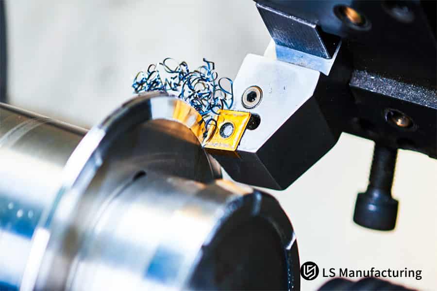
Figure 4: Showcasing the tooling and parts for accurate CNC turning services by LS Manufacturing
LS Manufacturing High-End Furniture Industry: Mass Production Project For Complex Carved Bedposts
In the following case study, which relates to high value manufacture, LS Manufacturing's competency is being made evident when the company is asked to produce intricately carved rosewood bed posts on a wholesale scale. It is a case study, in an effort to find our value in high-value manufacturing with precision solutions aimed at our high-value audience.
Client Challenge
For instance, for the production of luxury furniture, the demand was for a large number of bed posts made from rosewood with exquisite carvings on details that could not be achieved with conventional machining systems. This is because a carving depth of ±0.2mm was not feasible for a first-pass yield of only 85%. Additionally, an increase of 50% in the processing costs for every unit was expected.
LS Manufacturing Solution
The obtained outcome was made possible by the variation of the depth carvings to ±0.05mm, which enhanced the yield of the first pass to 98.5%. The life of the cutting tool was improved by 3 times, along with an increase in the cost of the production of goods by 40%, thus allowing the client to offer annual savings of over ¥600,000 to enter the market for the high-end product.
Results and Value
It is one of the examples that highlight the relevance of the capability of LS Manufacturing to provide value in terms of the depth of technology professionalism because we are in a position to provide effective answers to the challenges faced in the manufacturing sector through the use of industry-leading technology, thus making us competitors in terms of having a highly valuable audience in search of credible precision manufacturers.
Let it be noted as one among several examples pertaining to the way in which LS Manufacturing is capable of providing value on the subject of skill and engineering professionalism because of the success that our staff has experienced in this process; because our staff has been successful in overcoming the challenges that are experienced in manufacturing, making good decisions with the information we have, our clients benefit with a valuable audience that requires precision with respect to manufacturing services.
Struggling with the dual challenges of carving precision and cost? Our efficient processing solutions will help you achieve a simultaneous leap in both quality and profitability. Get your customized optimization plan today.

Practical Applications Of Advanced Testing Techniques In Quality Control Of Wooden Components
The conventional manual inspection systems used in the production of wood turning parts have shortcomings such as costs, subjectivity, and accuracy in detecting faults for maintaining quality control as far as mass production is considered. This document details how advanced inspection technologies address these limitations through systematic implementation:
Laser Scanning for Dimensional Verification
The accuracy of the high-resolution laser scanner is within ±0.02mm for scanning 3D point cloud data. Therefore, the entire product dimensionality is ascertainable. Automatic scanning is done to computer-designed models, with deviation between them for critical dimensions, for instance, joint areas of furniture, as well as surfaces identified. No human measurement and analysis, as well as CMM, is needed for this, which takes less than 2 minutes for each piece, contrary to 30 minutes for the manual method.
Machine Vision for Surface Defect Detection
Additionally, it should be noted that the integrated machine vision system along with multi-angle lighting systems supports defect recognition on the surface of the product that includes scratches, tear-outs, or grains. This technology utilizes intense machine learning models that had been trained on a large number of samples of different types of defects on the surface, guaranteeing a defect accuracy of over 99.9% for a defect size up to 0.1mm. This technology guarantees that all aesthetically pleasing criteria are carefully considered.
In-Line Integration and Data Management
The inspection systems are integrated with the entire production process, enabling 100% inspection of products without having to wait for the production process to complete. The information generated is recorded in real-time, which is stored within a central database, enabling traceability of the products from material to the product level. The software statim process control is used for analyzing trends.
The technical framework illustrates how advanced inspection solutions can make quality control not be a bottleneck, but rather a competitive advantage in mass production of wood components that offers the necessary information for improvements.
FAQs
1. What are the top three factors regarding the assessment of a CNC supplier for your woodworking projects?
Taking into consideration all the above, it can be said that: the key factors are equipment accuracy (spindle accuracy ≤0.01mm), process capability (Cpk ≥1.33) and a quality system (ISO certification).
2. How can different wood densities affect the parameters of the processing?
With the increase in material density, say by 0.1 g/cm3, the cutting parameters must vary by 15 to 20%. The databases of parameters for materials are already set up by experts.
3. How to ensure consistent accuracy when processing complex curved wooden parts?
5-axis linkage technology and special fixtures are used to realize positioning accuracy relative to geometric errors, with an on-line compensation system and the highest precision of up to 0.1mm.
4. How is variability of quality controlled for massive production?
These critical parameters are measured using SPC (Statistical Process Control), and the process capability index is always within the specified criteria.
5. Approximately how great is the percentage that tooling contributes to the total cost involved in woodworking?
Approximately 15% to 25%. This could be reduced by over 30% through tooling optimization. The tooling optimization ability within the supplier also needs to be evaluated.
6. What are the requirements for verification in the processing of new species of wood?
It is required to carry out a range of process verifications like process tests in cutting force, surface checks, and tool life verifications.
7. How to evaluate a supplier's ability to respond to urgent orders?
Analyze the flexibility of equipment, the production scheduling process, and rapid mold changes they are capable of. This should be done by professional molding companies within a period of 24 hours for emergency orders. If you have an urgent project, you can get a fast CNC machining quote online to test their turnaround capability.
8. In what respects might the key points for preventing deformation of wood components be generalized?
It involves processes such as moisture content management (8-12%), stress relief, and optimization of the clamping arrangement.
Summary
Through a scientific technical evaluation system and detailed processing data, companies can accurately assess the true capabilities of CNC turning suppliers and choose partners with professional technical strength and a complete quality system.
For customized woodworking solutions or supplier capability assessment reports, please contact LS Manufacturing technical team. We will provide you with professional technical support.
Get professional CNC wood turning service solutions. Contact the LS manufacturing team today to empower your project with precision.
📞Tel: +86 185 6675 9667
📧Email: info@lsrpf.com
🌐Website: https://lsrpf.com/
Disclaimer
The contents of this page are for informational purposes only. LS Manufacturing services There are no representations or warranties, express or implied, as to the accuracy, completeness or validity of the information. It should not be inferred that a third-party supplier or manufacturer will provide performance parameters, geometric tolerances, specific design characteristics, material quality and type or workmanship through the LS Manufacturing network. It's the buyer's responsibility. Require parts quotation Identify specific requirements for these sections.Please contact us for more information.
LS Manufacturing Team
LS Manufacturing is an industry-leading company. Focus on custom manufacturing solutions. We have over 20 years of experience with over 5,000 customers, and we focus on high precision CNC machining, Sheet metal manufacturing, 3D printing, Injection molding. Metal stamping,and other one-stop manufacturing services.
Our factory is equipped with over 100 state-of-the-art 5-axis machining centers, ISO 9001:2015 certified. We provide fast, efficient and high-quality manufacturing solutions to customers in more than 150 countries around the world. Whether it is small volume production or large-scale customization, we can meet your needs with the fastest delivery within 24 hours. choose LS Manufacturing. This means selection efficiency, quality and professionalism.
To learn more, visit our website:www.lsrpf.com.