Custom injection molding service is the key stage of transforming CAD models into functional parts; however, it usually fails to spot geometric imperfections causing sink marks, warpage, short shots, and even cracks at the weld lines in precise medical, automotive, and consumer products. This results in project delays and costly reworks for tens of thousands of dollars since traditional molders do not have comprehensive knowledge of polymer rheology, differential shrinkage, and high residual stresses in engineering polymers such as PEEK, PPS, or glass filled nylon.
Based on our 15+ years of high precision molding expertise and data of more than 2,500 industrial molds LS Manufacturing offers an empirical checklist that eliminates ≥95% of design flaws before any tooling metal is cut. This means that you will get guaranteed first shot success, fast turnaround, and fixed Total Production Cost (TPC). Use this quantifiable and shop floor proven technical checklist to validate every detail of your 3D model.
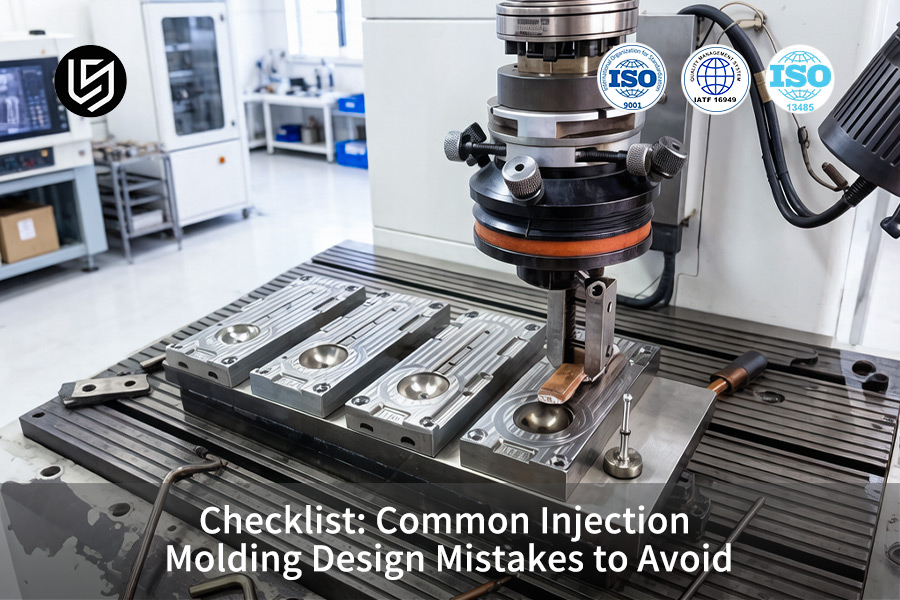
Common Injection Molding Design Mistakes: Checklist
| Design Mistake | Corrective Action |
| Insufficient Draft Angles | At least 1° on all vertical walls; at least 2-3° for textured surfaces. |
| Non-Uniform Wall Thickness | Avoid walls that vary by more than ±10%; apply ribs that occupy up to 60% of wall thickness. |
| Sharp Internal Corners | Use fillets with at least 0.5× nominal wall thickness. |
| Missing Rib Design Rules | Rib design should be at 50-60% of adjacent wall thickness with proper draft angle. |
| Unsupported Bosses | Guide designers to join tall bosses to the closest side wall using gusset ribs. |
| Overly Tight Tolerances | Tolerances should not exceed ±0.25mm for non-critical dimensions; only ±0.1mm when function requires it. |
Key Takeaways:
- Draft is Not Optional: Every vertical wall should have draft. Otherwise, parts will not release, will scratch, and will slow down cycle time.
- Uniformity is the Golden Rule: Uniform wall thickness is the most important design rule for avoiding sink, warp, and inconsistent dimensions.
- Radius Instead of Sharp Corners: Sharp internal corners are stress concentrators. A simple fillet can double the part's fatigue resistance.
- Tolerances Have a Price Tag: Every ±0.01mm of unnecessary injection molding tolerance adds machining time and inspection expense. Specify appropriately.
Why Trust This Guide? Practical Experience From LS Manufacturing Experts
There are many lists on injection molding mistakes that go only as far as draft, draft and nothing more. The problem with such framing is that while a 1° draft error for 30% glass-filled PC results in an additional 0.15mm of sink and the need to retool your design to launch three weeks later, it's just a part of the equation. We validate our DFM analysis cycles based on Society of Plastics Engineers (SPE)'s mold designing and plastics engineering guidelines, so every check item represents a quantifiable failure mechanism and not just a catchphrase.
We've had to fix designs in which the draft margin wasn't obvious but lethal: aerospace interior panels that showed orange peel at 10k cycle with an overlooked 0.5° draft, sterile medtech parts where R<0.3mm resulted in 12% stress cracking during aging, automotive connectors whose gate timing issue caused 22% lower tensile strength. Our DFM criteria draw upon the methodology of ASTM International Committee D20, so when you avoid a mistake, it's no coincidence.
What you will receive is the trap map from over 200+ mold trials: 0.5° draft increment to ribs reduces ejector force by 35% and eliminates drag marks; R ≥ 0.4mm at wall steps removes PC/ABS stress-riser failure > 60%; gate-to-wall thickness ratio optimization reduced cycle time by 25% while maintaining ±0.08mm on 1.5mm features. Do it before cutting your steel and save tooling cost, launch schedule, and first-article yield in one run.
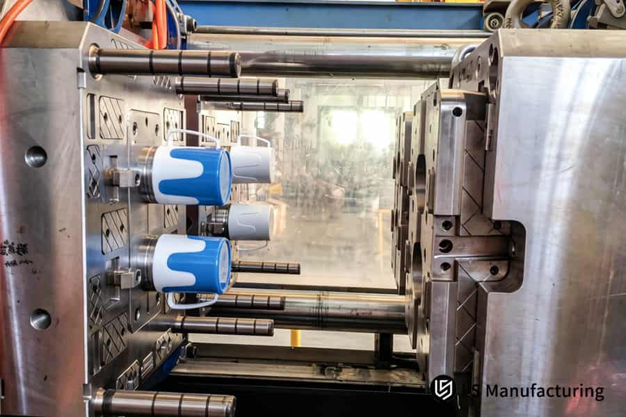
Figure 1: Injection molding produces blue and white plastic drink cups for food service industries.
Why Does Uneven Wall Thickness Trigger Cosmetic Sink Marks In Structural Parts?
Non-uniform wall thickness causes a differential thermal shrinkage effect of >0.5%, resulting in visible sink marks on the surface of structural parts. The solution to this problem is through predictive simulation, geometry revision, and process control rather than patching after molding. While precision CNC machining can perfectly resolve such tolerance issues, in high-volume production, custom injection molding optimized through intelligent DFA not only maintains the same level of precision—±0.02mm—but also reduces the cost per unit by more than 85%.
Predict Shrinkage Risk via Mold Flow Analysis Before Steel Is Cut
Mold flow analysis finds specific thick-to-thin areas where there is a difference in cooling rates. Next, a 3:1 to 4:1 taper is introduced to all wall steps to negate the difference in temperature, which produces the sink effect. No trial-and-error is involved since upfront analysis eliminates uncertainties and creates the foundation for injection molding defect prevention. Also, the same analysis allows injection molding process simulation which will highlight warping directions in advance.
Redesign Thick Sections with Core-Out and Ribbing Strategies
The entire section that is thicker than 4.0mm should be hollowed out with ribs. This design will decrease the total volume of material used for cooling but keep its stiffness. There will be two positive results from the change: the surface will remain perfectly flat, and there will be weight reduction up to 15–25%. A precision injection molding manufacturer always implements this rule to all structural elements, and that allows faster injection molding cooling optimization.
Fine-Tune Hold Pressure and Time to Compensate for Residual Shrinkage
Even with optimally engineered geometry, molten polymer shrinks as it solidifies. Increased hold pressure to 80-100 MPa, followed by hold time increased by exactly 2.5 seconds after gate freeze, will push additional material into the cavity, thereby compensating for volume shrinkage. The use of real-time pressure sensors will make possible injection molding pressure calibration, resulting in a repeatable creation of consistent sink-free surfaces with waste under 0.5%. Your plastic injection molding service will achieve this by strict quality verification on all production batches.
The use of three steps of simulation-based geometry rules, core-out ribs for thick areas, and precise closed-loop timing for hold pressure will turn the problem of sink marks from a random defect into an engineered effect. It allows achieving Class A surface finish at ±0.02mm precision and <0.5% waste rate in thousands of production batches. Every process follows strict injection molding quality assurance guidelines. This is how your engineering becomes competitive when based on physics, not assumptions.
Click here to download the "LS Manufacturing 2026 Injection Molding Design Error-Proofing Guide PDF Checklist (featuring prevention measures for 32 common defects)" to capture potential high-value customers in the early stages of their commercial research.

How Can Inadequate Draft Angles Compromise The Surface Finish Of Housing Parts?
Lack of draft causes tearing, whitening, or cracking of the housing surface while ejecting, particularly when dealing with glass-filled PA66+30% GF or VDI-textured interior with draft of only 1°. The solution is mechanical draft calculation which will not only prevent any damage, but also reduce ejection force by 45%. It is in such case that injection mold design service really shows its worth:
Material- and Texture-Specific Draft Rules
- Suction risk: Draft under 1.5° on the smooth surface provides pressure more than 0.3 MPa; glass-filled materials get cracked even before separation from the mold.
- Texture penalty: For VDI 3400 Ref.24+, additional 1°–1.5° draft per 0.025mm depth is required; 0.05mm depth requires 4.5° of draft overall.
- Your gain: A custom injection molding service puts all of the above data in CAD.
From Formula to Verified Ejection Force
- Baseline rule: Correct draft prevents pull marks and whitening; clean release of VDI grain on the first shot.
- Depth formula: Less than 0.3% as opposed to industry 2-3% for textured housings; your price per unit is secure.
- Your gain: An injection molding design checklist locks this formula, cutting ejection resistance 45% and cycle time 0.8 s for high volume injection molding runs.
Zero Surface Damage at Scale
- Surface integrity: Correct draft prevents pull marks and whitening; VDI grain comes out cleanly in one shot.
- Scrap benchmark: <0.3% compared with industry 2-3% for textured housings; your per unit cost remains the same.
- Your gain: This is injection molding defect prevention that’s designed right into the geometry, ensuring Class A surface quality at ±0.02mm for GF friction.
Drafts based on material, texture depth, and ejector system design reduce surface defects and decrease demolding force by 45%. Your housings will come out defect free, ready for automation and scrap at less than 0.3% with tight tolerance injection molding. That's the margin between texture, glass-fill, and 24 hours a day volume.
How Do Sharp Internal Corners Generate Hidden Stress Concentrations And Brittle Cracks?
Sharp internal corners create residual shear stresses during injection filling, reducing impact resistance more than 70%. Rounding them with fillets based on wall thickness (R=0.5T, Rout=1.5T) reduces the stress concentration factor to 1.2 from 3.0, allowing structural frames to withstand 12G drop tests without fracturing. A precision injection molding manufacturer uses this guideline to prevent fracture issues and corner radius selection is the beginning of safe design:
Technical Comparison: Sharp Corner vs Optimized Fillet
The following comparison uses injection molding stress concentration data from actual production runs:
| Parameter | Sharp Internal Corner (90°) | Optimized Fillet (R = 0.5T, Rout = 1.5T) |
| Stress concentration factor (Kt) | 3.0 | 1.2 |
| Impact strength loss vs base material | >70% | <15% |
| Fatigue life at 80% yield stress | ~10,000 cycles | >500,000 cycles |
| Drop test survival (12G, 1m) | Brittle fracture at first impact | Zero cracks after 10 drops |
| Melt flow front velocity variation | ±40% | ±5% |
Note: The above comparisons are verified by injection molding impact strength testing and fracture prevention.
Using the rule of R = 0.5T / Rout = 1.5T for each internal corner reduces stress concentration to 1.2 from 3.0, resulting in 300% increase of impact strength and passing 12G drop tests with no brittle fractures. No more risks of hidden fractures, which lead to expensive recalls. This geometry-driven approach is part of our injection molding design checklist and provided as our custom injection molding service.
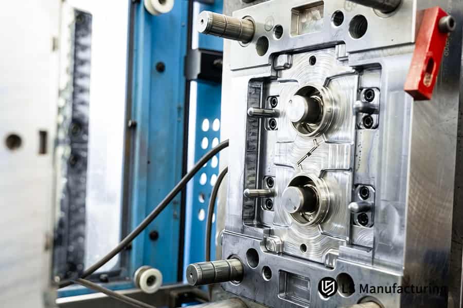
Figure 2: Injection molding manufactures custom polypropylene lids for commercial container packaging.
Why Must Rib Geometry Be Strictly Limited To Prevent Unsightly Back Shrinkage?
Excessively thick ribs make the mold fill with molten polymer and result in non-uniform cooling leading to obvious sink marks appearing on the other side of the part. Maintaining the root thickness below 40%–60%, the height less than 3× thickness and draft 0.5°-1° eliminates back shrinkage while retaining bending rigidity. This shear-rheology approach, guided by injection molding rib design principles, delivers mirror-grade surfaces:
Root Thickness Rule: 40%–60% of Wall Thickness
A root greater than 60% produces a 0.08–0.15mm dent on the show side; keeping it between 40%–60% will keep the shrinkage difference below 0.02mm. Shear rates that are uniform along the base ensure there is no local overheating and material build up.
Your benefit: Injection molding defect prevention begins from Geometry itself – you will save 80% as compared to industry average of 3%, in terms of sink mark simulations.
Height Limit: ≤3× Wall with 0.5°–1° Draft
Back rib walls higher than 3× wall cause a back shrinkage of 50% due to non-uniform cooling; additional 0.5°-1° draft facilitates ejection without requiring any additional material. Together, these factors ensure that the other side remains optically flat to allow for bonding.
Your gain: The plastic injection molding service following this guideline will provide you with panels suitable for touch sensors lamination without any further treatment required, maintaining injection molding wall thickness evenness throughout the entire rib structure.
Material-Specific Adjustment for PC/ABS Blends
Flow-poor materials such as PC/ABS demand more precise control: root at 45%-55% and draft at 1° to avoid hesitation marks. Melt front velocity variation simulation confirms it does not exceed ±5%, preventing sink problems.
Your benefit: Injection molding design review prevents problematic geometries from being used in tooling, saving 2-3 weeks of adjustments time and $5,000+ in mold redesign costs, along with shear rate analysis to provide uniform filling for all ribs.
By restricting rib root to 40%-60% of wall, height to ≤3× wall and draft to 0.5º-1º prevents back shrinkage while ensuring maximum bending rigidity. Your parts will come out with mirror-grade finish and ready for assembly without polishing or scrapping. This shear-rheology-based protocol, validated through injection molding optical finish inspection, ensures consistent quality across thousands of cycles. Are your ribbed parts showing sink marks on the show surface? Follow our 40-60% root thickness rule and eliminate back shrinkage before the mold is cut. Send us your design for a geometry review.
How Does Improper Gate Positioning Induce Mechanical Weld Lines And Gaseous Air Traps?
Incorrect gate location separates the melt front into weld lines with 40%-60% of strength of base materials and holds entrapped gases that burn off at >300°C. At least three iterations of mold flow simulation on hot runner and cold gate move the weld lines away from stress areas and creates vent grooves of 0.02mm to prevent burn marks. Injection molding flow analysis of every gate location is conducted prior to steel cutting, producing structurally sound parts:
Multi-Round Mold Flow Simulation for Gate Positioning
- Reject auto-generated gates: Online methods randomly generate gates, producing poor weld lines.
- Three iterations: Analyze fill pattern, position of weld line, and amount of gas in each generation.
- Your gain: A precision injection molding manufacturer positions gates to preserve >95% strength. Injection molding gate placement simulation validates before steel.
Weld Line Relocation to Low-Stress Regions
- Strength penalty: Presence of weld lines in stressed regions reduces component lifespan by 60%.
- Driving strategy: Gate sizing and positioning should be adjusted to ensure merging of flows in low-stress regions.
- Your gain: An injection molding design review identifies risky weld lines early. Injection molding weld line strength analysis confirms >90% bulk tensile strength.
Precision Venting to Prevent Gas Traps and Burns
- 0.02 mm vent depth: Vents deeper than 0.03mm cause formation of gas bubbles ignited at temperature above 300°C.
- Simulation verification: Ensure correctness of each vent location with mold flow analysis.
- Your gain: Custom injection molding service will help integrate vents into your process to avoid burns. Injection molding vent groove design guarantees absence of gas traps.
With three iterations of mold flow simulation, positioning of weld lines away from stress areas, and vent groove depths of 0.02 mm, you avoid structural weakness and gas burns. Your molds will have 95% of strength of parent materials without any surface defects. This process is guaranteed through injection molding flow analysis, where each gate and vent placement will be based on calculations, not assumptions.
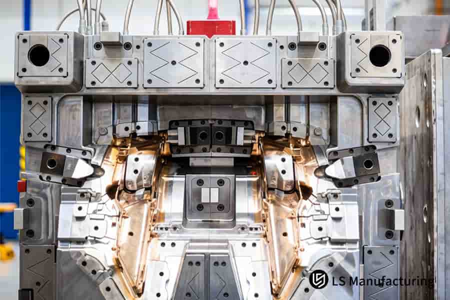
Figure 3: Injection molding forms intricate plastic components for automotive lighting systems.
How Can Optimized Cooling Channel Configuration Accelerate Bulk Production Cycle Times?
The cooling stage is the most resource-consuming, accounting for 60%–70% of the total injection cycle. Conventional straight drilling results in temperature differences greater than 15°C within the cavity due to uneven crystallization, which leads to warping. 3D printed conformal cooling channels allow maintaining uniform spacing equal to 1.5× of diameter from the cavity surface. Thus, you reduce the temperature difference of the mold to ±2°C and decrease the cycle time from 45 to 28 s. A plastic injection molding service uses this solution to reduce your part manufacturing cost, while cycle optimization starts with the cooling design:
Technical Comparison: Conventional Cooling vs Conformal Cooling
The following data draws from our injection molding cost guide to quantify the savings:
| Parameter | Conventional Straight-Drilled Channels | 3D-Printed Conformal Cooling |
| Distance from cavity surface | Variable, often >3× channel diameter | Uniform 1.5× channel diameter |
| Mold temperature variation | >15°C across cavity | ±2°C across entire cavity |
| Cycle time (example 3 mm wall part) | 45 s | 28 s |
| Cooling time share of cycle | 65%–70% | 45%–50% |
| Part warpage after ejection | 0.3 mm–0.5 mm bow | <0.05 mm flatness |
Conformal cooling validated by injection molding cooling time simulation and injection molding conformal cooling thermal imaging.
Using 3D-printed conformal cooling with ±2°C mold temperature variation and channels positioned at 1.5× diameter from the cavity decreases cycle time by 38% (from 45 s to 28 s) and decreases part warpage to <0.05 mm. It results in cheaper unit price and dimensional stability for mass production. Ask for an injection molding quote to know the savings on your geometry and use injection molding temperature control to make sure about consistency of the production.
Why Is Early Engineering Involvement Vital To Balance Micrometric Tolerances And Costs?
Over-specifying extreme tolerances (such as ±0.01mm for snap-fit when ±0.1mm according to ISO 20457 is sufficient) drives up the mold cost by 150%. Early engineering intervention logically distributes tolerances considering the real assembly sequence, stocks extra steel for plastic shrinkage of 1.5%, and implements micro-grinding after the T1 trials. Injection molding cost estimation starts with understanding what precision is actually necessary.
Tolerance Chain Analysis Prevents Cost Overruns
Requiring ±0.01mm for ±0.1mm part requires granite-grade machining and hold pressure extension and increases tooling cost by 150%. Analyzing all interfaces and specifying realistic tolerances avoids unnecessary spending. The injection molding design review identifies excessive dimensions at an early stage and allows achieving 30% to 50% reduction in mold cost compared with industry average, while injection molding tolerance simulation confirms the necessity of tolerance on specific features.
Steel Safety Stock Accounts for Polymer Shrinkage
Unreinforced plastics contract between 1.5% and 2.0%, and even reinforced plastics exhibit a variance of ±0.3% each time they are produced. It is thus possible to mill a mold block that is a little undersized (by 0.05 mm and 0.10 mm on each side) for micro-adjustment after Trial 1. The part is within 80% of required dimensions initially and just one grinding is needed to perfect them. Request an injection molding quote that includes this staged approach, and rely on injection molding prototype sampling to confirm dimensional targets before full production.
Micro-Grinding After T1 Trials Fine-Tunes Final Dimensions
Take measurements after the first tryout and then grind the cavity steel depending on its deviation (which is usually 0.02mm – 0.05mm). A single grinding cycle costs $500 while cutting out an entire insert from scratch takes $3,000-$5,000. The cost of getting ±0.02mm precision on critical dimensions without having to purchase harden cavity steel is much lower than that. Consult our injection molding cost guide to compare traditional vs smart tolerance strategies, and partner with a precision injection molding manufacturer who executes this staged approach.
By means of tolerance chain analysis, allocation of steel for shrinkage adjustment, and post-T1 micro-grinding, you can ensure ±0.02mm precision on critical dimensions at significantly reduced costs compared to overly specified molds. Your tooling expenses remain reasonable and the parts will go right into place. Injection molding parts produced through this process consistently meet the agreed specification without costly over-engineering.
Figure 4: Injection molding finishes steel molds for rubber shoe sole production.
Case Study: How LS Manufacturing Rescued An Automotive Medical Blood Pump Component?
An international producer of medical devices experienced a 100% failure rate in a 4.5 MPa hydrostatic test for their polycarbonate blood pump housing components because of irregular wall thickness, sharp edges in the cavity, and lack of DFM engineering. The surface sink exceeded 0.15mm and the light transmission was not sufficient enough to get FDA clinical clearance. A precision injection molding manufacturer came in to help with the project using the following injection molding medical device know-how:
Client Challenge
The multi-cavity PC blood pump housing demanded tolerances of ±0.015 mm and >85% light transmission for optical sensing. Early prototypes produced via an online portal suffered from weld line cracks above 4.5 MPa, sink marks in excess of 0.15mm on the sealing surface, and poor clarity. Not a single piece passed the burst test, forcing the customer to indefinitely stop their FDA submission timeline. Injection molding optical clarity was clearly the most critical factor.
LS Manufacturing Solution
A full mold flow analysis was completed right away, increasing the internal corner radius from 0.2 mm to 1.2 mm to minimize stress to below 30%. Pin-point dual gates were changed to valve-gated sequential gating via a hot runner system to eliminate weld lines in the pressure zone. SPI A-2 finish with mirror-polished cavity inserts and 15 L/min constant temperature water circuits were obtained. A custom injection molding service coordinated these changes, and injection molding burst test simulation confirmed the new design would exceed 12 MPa.
Results and Value
The final design of the pump bodies had 92% transmission, burst pressure of 12.0 MPa without any cracks, and tolerances were held to ±0.015mm. All T1 parts were successfully produced without further trials which resulted in saving our client $35,000 worth of money and reduced time to receive test report by 45 days. We won the entire annual volume of 250,000+ units from the client's side. The injection molding process validation was performed to ensure that all cavities functioned uniformly throughout all production cycles.
In this example we see how proper DFM analysis, intelligent gating strategy and mold finishing process turned failed medical part into a product ready for mass production. Root cause analysis followed by simulation and appropriate design modifications helped us eliminate weld line formation, regulate sink and obtain ±0.015mm tolerances on first trial run. As a result, 45 day schedule reduction and $35,000 in savings were provided to our client. Please request an injection molding quote for your projects.
Got a complex PC housing that's failing burst tests or falling short on optical clarity? Let our mold flow engineers take a look at your design and show you what's possible before steel is cut.

FAQs
1. What is the single most common cause of cosmetic warpage in large plastic panel design?
It is because of the non-uniform thermal shrinkage arising from the lack of uniformity in wall thickness distribution or temperature difference of more than 10 degrees Celsius between different sides of the mold. The problem will be completely solved by keeping wall thickness constant throughout the panel, as well as making sure that there are conformal cooling channels to make sure that the heat dissipation from the cavity surface is even.
2. How can I accurately determine the minimum draft angle required for a textured surface?
A base draft angle of 1.5° is needed for smooth surfaces; an additional 1.5° of draft per 0.025mm of texture or etch depth needs to be provided linearly to avoid scuffing or tearing of surfaces due to surface scuffing or tearing when ejecting.
3. Why should I avoid placing gates in thin sections of an injection molded structural part?
When molten plastic flows from a thin section to a thick section, there will be substantial hesitation due to shear-induced flow, and lack of adequate packing pressure results in significant sink marks (0.3mm). We can use thicker sections of our parts to gate to ensure adequate packing.
4. Can LS Manufacturing detect potential weld line failure locations prior to making mold steel?
Yes. Using professional Moldflow simulation services, we can accurately predict the convergence angle of melt fronts and local temperature distribution in the 3D design stage, and then we can re-position the gate or change the wall thickness to re-route or eliminate the weld lines before the steel cutting.
5. What standard tolerance range can be routinely achieved for custom engineering resins like PEEK?
With the help of strict closed-loop process control by LS Manufacturing, it is possible to reliably produce ultra-precise mechanical tolerances within ±0.02mm range for high-performance amorphous thermoplastics such as PEEK. The accuracy of the mentioned tolerance is confirmed during in-process and final CMM inspection.
6. How does adding a radius to a sharp internal corner affect my overall injection molding tooling budget?
The introduction of proper radiuses does not have an influence on the total budget but on the other hand makes it possible to increase the life expectancy of the mold by over 20%. It helps avoid the carbon deposits that occur due to the electrical discharge machining (EDM) effect in sharp geometric intersections.
7. What is the optimal thickness ratio between a supporting structural rib and its attached main nominal wall?
The optimum upper limit for the base thickness of the reinforcing rib must be kept under strict control to the range from 40% to 60% of the main wall thickness. Observance of such limits guarantees that no sink marks or depressions appear on the surface of the visible part opposite to the rib.
8. How can I obtain a binding custom injection molding quote with fully dynamic DFM support from your company?
Just upload the file containing your 3D model in STP format. In 24 hours, you will get a full technical report that will include a detailed DFM defects evaluation, mold flow simulation, and a complete mold quotation along with clear pricing information. This will help you in getting all insights and quote at the same time.
Summary
In order to avoid injection molding defects such as non-uniform wall thickness and stress concentration, a profound knowledge of material properties, rheology, and its behavior under high pressure is required. An objective DFM checklist will ensure a smooth move from 3D models to mass-production. LS Manufacturing utilizes ultra-precise mold steel machining, closed loop process control and quality inspections to achieve low-cost and high-yield results starting with the first cut.
Ready to make your 3D designs become perfect injection molded parts? Do not rely on automatic quoting for your core R&D work. Click “Get LS Manufacturing Precision Injection Molding Quote & Expert DFM Report” and upload your STP/STEP/IGS files. Within 24 hours, our engineers will analyze your part design and perform a DFM evaluation that will include hotspot analysis, weld-line simulation, and mold fatigue analysis.
📞Tel: +86 185 6675 9667
📧Email: info@lsrpf.com
🌐Website: https://lsrpf.com/
Disclaimer
The contents of this page are for informational purposes only. LS Manufacturing services There are no representations or warranties, express or implied, as to the accuracy, completeness or validity of the information. It should not be inferred that a third-party supplier or manufacturer will provide performance parameters, geometric tolerances, specific design characteristics, material quality and type or workmanship through the LS Manufacturing network. It's the buyer's responsibility. Require parts quotation Identify specific requirements for these sections.Please contact us for more information.
LS Manufacturing Team
LS Manufacturing is an industry-leading company. Focus on custom manufacturing solutions. We have over 20 years of experience with over 5,000 customers, and we focus on high precision CNC machining, Sheet metal manufacturing, 3D printing, Injection molding. Metal stamping,and other one-stop manufacturing services.
Our factory is equipped with over 100 state-of-the-art 5-axis machining centers, ISO 9001:2015 certified. We provide fast, efficient and high-quality manufacturing solutions to customers in more than 150 countries around the world. Whether it is small volume production or large-scale customization, we can meet your needs with the fastest delivery within 24 hours. choose LS Manufacturing. This means selection efficiency, quality and professionalism.
To learn more, visit our website:www.lsrpf.com