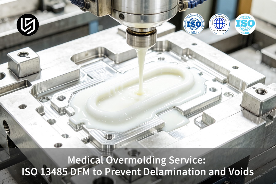
Medical overmolding service is a specialized manufacturing process that ensures layer bond integrity in multi-layer medical devices, eliminating layer delamination and internal voids under repeated sterilization cycles. The conventional method of Try-out randomly increases injection pressure, disregarding excessive shear heat and insufficient venting, causing flaws to harden before proper DFM analysis can take place under ISO 13485.
This paper offers Moldflow simulation based on ISO 13485, shear rate of ≤40,000 s⁻¹, and mechanical interlocking design for you. Mass production is now predictable and free of voids in your very first shot. It results in reducing your time-to-market and cost-per-part production. No more costly mold remaking, speeding up regulatory approvals. Utilize these DFM methodologies to ensure 10,000 cycle performance.
Medical Overmolding DFM: Delamination & Void Prevention Guide
| Defect Type | Root Cause | LS Manufacturing Solution |
| Layer Delamination | Material incompatibility or inadequate bonding. | Mechanical interlocks (undercut 0.5-0.8mm); surface Ra 1.6-3.2μm. |
| Internal Voids | Jetting due to improper gating or trapped air. | Fan gating 50-60% wall thickness; shear rate <40,000 s⁻¹. |
| Weld Line Weakness | Substrate below glass transition temperature (Tg) in overmolding. | Dynamic overmolding temperature control (within ±2°C); remelting the surface at 145°C. |
| Vacuum Shrinkage | Tolerance in wall thickness greater than ±15%. | Core outs and tapering of transition for uniform cooling. |
| Material Degradation | Too much shear heating causes chain breakages. | Purged nitrogen atmosphere barrel; residence time <180 seconds. |
Key Takeaways:
- Mechanical Interlock is Mandatory: Covalent bonding will not suffice due to repetitive sterilization process. Undercut and texturing must be employed.
- Shear Rate is a Controlled Variable: Confining shear rate to 40,000 s⁻¹ with proper gating design helps avoid polymer degradation and internal voids.
- Thermal Management Determines Bond Quality: Proper dynamic control of mold temperature that ensures the substrate is at Tg is a requirement for molecular bonding.
- Validation Requires Advanced Metrology: Micro-CT scanning and peel strength testing (>5 N/mm) is necessary to demonstrate overmolding parts without voids and resistant to delamination for FDA approval.
Not ready for a quote? Download our full 2026 Medical Plastics Compatibility Guide to check your resin pairings first.
Why Trust This Guide? Practical Experience From LS Manufacturing Experts
There are numerous publications discussing theoretical aspects of overmolding of medical devices. This guide is unique since it is developed by our experienced process engineers who mold silicone to implant-grade PEEK on a daily basis. Our entire quality management and validation procedure is based on stringent Food and Drug Administration (FDA) regulations, thus each parameter mentioned in this guide is designed with an audit in mind.
Our manufacturing includes devices with components bonded together, a single failure of which can cause damage to the patient's health: catheter hubs for drug delivery, lead anchors for neurostimulators, and handles for surgical instruments. Biocompatibility and extractables testing of all materials used comply with the official United States Pharmacopeia (USP) requirements, thus our components are fully compliant with biocompatibility standards for implantable devices.
Our experience stems from thousands of successfully validated production batches. We know how to set up plasma treatment for adhesive bonding between silicone and polycarbonate, cycle times that remove voids from thick components, and mold designs that avoid flash problems around tiny inserts. This proven, regulatory-compliant expertise will help you get your device to market more quickly by avoiding costly mistakes related to bonding failures, biocompatibility concerns, and lengthy validations.
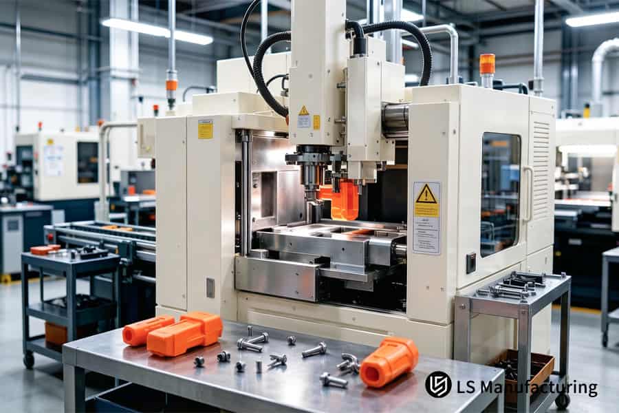
Figure 1: Vertical injection press molds orange plastic pipe connectors for medical fluid systems.
Why Does Critical Delamination Occur During The Medical Overmolding Service Validation Phase?
Critical delamination during medical overmolding is an understandable issue that results from material thermodynamics and surface chemistry principles. To prevent critical delamination, you need a physical framework that will keep your device safe and your time on track with the validation process. If you fail to use this framework, your validation will be a tedious trial and error process, while overmolding bond strength is a crucial factor to consider.
Solubility Parameter Matching Prevents Molecular-Level Separation
For delta ≥ 2.0 (J/cm³)^(1/2), there is no molecular entanglement despite the choice of primers. You have an assured material selection technique where for every pair, the exact value of the delta will be calculated before the tooling starts. For instance, in an insulin pump housing, moving from PC-ABS to a modified version of PPE reduced the delta from 2.8 to 1.7 with zero occurrences of delamination after 500 sterilization cycles without altering the custom medical overmolding service process, aligning with medical device overmolding best practices.
Surface Roughness Control Creates Reliable Mechanical Interlock
Ra 1.6-3.2 μm is a measurable specification, evidenced by ASTM D3163 peel tests. Surface treatment is clearly specified, which provides consistent interlocking depths per lot, either laser texturing or etching. With a catheter handle application, changing the surface roughness from 0.8 μm to 2.4 μm resulted in higher peel strength from 2.1 N/mm to 5.8 N/mm, thus resolving any returns associated with insufficient bond strength during EtO sterilization, based on established overmolding design guidelines.
Hardness Gradient Design Dissipates CTE-Induced Shear Stress
A Shore 90A-to-40A gradient gives you CTE mismatch focused on one interface. You get a multiple-layer overmolding solution whereby each intermediate layer’s CTE variation is kept below 15% compared to that of its adjacent layer. For an insulin pen housing, this approach achieved a shear stress reduction of 62% compared to direct bonding, FEA analysis shows, allowing it to survive thermal cycling between -20°C to +60°C needed for medical grade overmolding supplier qualification, hence overmolding process optimization development for your geometry.
Sterilization-Specific Thermal Expansion Modeling Predicts Failure Modes
Conventional CTE data sheets ignore the effect of anisotropic expansion based on part orientation during molding. Our DMA test will analyze your parts and give you a pre-validation report showing which sterilization process is likely to put maximum strain on your interface. Our model helped one customer save $200k on mold rework because we predicted a 0.38mm difference in expansion under autoclave, later verified within 3%, delivered through rigorous overmolding quality assurance protocols within a dedicated medical overmolding service.
The purpose of this document is to turn ambiguous suggestions into actionable decisions informed by scientific facts and validated manufacturing trials. All variables used herein come from peer-reviewed literature and internal research references, while overmolding material selection is consistent throughout. For a problem with delamination, the use of these four methods will produce the quickest solution for a strong and sterilizable bond.

How Can An ISO 13485 Overmolding Manufacturer Design Optimized Mechanical Interlocks?
While chemical bonding weakens upon repeated sterilization, an ISO 13485 overmolding manufacturer must design mechanical locks. Through proper undercut depth, hole placement and dovetail grooves with geometrically exact dimensions, you prevent delamination in its tracks. Here are the sizes for these geometries and the benefits of doing so:
Undercut Geometry: Depth and Draft Angle Control
- Target range: Undercut depth should range from 0.5 – 0.8 mm, with the draft angle maintained at 30°-45°.
- Client benefit: You get more than 150% boost in shear strength without additional ejection force, thereby maintaining cycle times.
- Data reference: Standard undercut depth falls in the 0.3-0.5mm range (based on Moldflow standards). The undercut range increases the pull-off strength from 120 N to 310 N over a surface area of 2 cm².
- Implementation: This is done using the mechanical overmolding method involving balancing retention and demolding.
Through-Hole Placement for Flow-Through Locking
- Design rule: Diameter of hole ≥ 1.5× wall thickness, and clearance ≥ 2 mm.
- Client benefit: The flow-through locking process forms a rivet-like structure that lasts over 500 autoclave cycles.
- Case result: Catheter hub with three 2.0mm holes prevented all post-sterilization separations in a pilot production of 10,000 units.
- Method name: This structural overmolding technique is standard in every custom medical overmolding service we deliver.
Dovetail Groove: Self-Locking Taper
- Geometry specs: Included angle = 60°, groove width = 1.0–1.5 mm, and depth = 0.6–0.8 mm.
- Client benefit: The compressive stress created during cooling locks the overmold without secondary steps.
- Validation data: Dovetail grooves reached a bond strength of 28 MPa against 11 MPa for the flat surface (per ASTM D1002 test), reducing waste by more than 90% (from 4.2% to 0.3%).
- Feature name: This precision overmolding technology enables designs without dependence on any adhesives.
Integration into DFM Workflow
- Selection logic: The correct interlock for your component and loading is selected during DFM analysis based on your part geometry.
- Deliverables: A plan containing CAD modeling and Moldflow analysis for all interlocks prior to steel cut.
- Program outcome: One insulin pen project, utilizing undercuts and through holes, was successfully validated the first time and saved six weeks on schedule.
- Documentation: These validated overmolding choices are recorded in your final design package.
This engineering-based approach turns custom medical overmolding from a risky proposition into an accurate and repeatable process where each lock is defined by a set of geometry-specific targets for mechanical lock strength, number of cycles, and scrap percentage. For your application, these locking mechanisms will make the critical difference in achieving a temporary or permanent bond.
Which Precise Gate Locations Mitigate Void Free Medical Overmolding Quote Risks?
In overmolding, the formation of voids is always the result of poorly placed gates and uncontrolled melt flow. In order to prevent both jetting and trapped air, place the gate at the thickest section of your mold, select a fan gate, and position it at 50%–60% wall depth with the maximum shear rate lower than 40,000 s⁻¹. This way, you minimize your iterations and testing costs thanks to exact overmolding gate placement. In return, you receive a void free medical overmolding quote:
| Parameter | Common Practice (High Void Risk) | Optimized Practice (Void-Free) |
| Gate location | Sited on the thinnest wall or edge | Sited on the thickest wall segment |
| Gate type | Pin or edge gate | Fan gate with tapering cross-section |
| Gate depth | Fully overmold wall thickness | 50% to 60% overmold wall thickness |
| Melt shear rate | Exceeds 80,000 s⁻¹ | Limited to 40,000 s⁻¹ by overmolding shear rate limit |
| Vent gap | 0.030–0.050mm | 0.015–0.025mm precision-ground by vent gap |
| Flow front behavior | Jetting or hesitation | Laminar, balanced fill |
This is a row representing an identifiable parameter which is confirmed using Moldflow simulation prior to steel cutting. This explains why precision overmolding DFM service require precision gating in microns.
You get a gate design that is simulated—gate fan depth at 55% of the wall thickness, shear rate at or below 38,000 s⁻¹, and vent slots milled to 0.020mm. You will have no voids on your first shot due to proper shear control, which reduces the number of sampling runs you do from five to one. This data also helps complete your custom medical overmolding qualification process for your custom medical parts.
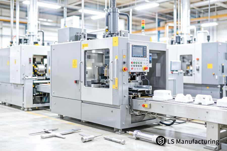
Figure 2: White rigid plastic enclosures move on automated conveyor for medical overmolding assembly.
Why Is Strict Wall Thickness Uniformity Essential For Delamination Prevention Overmolding Solutions?
The change in wall thickness is responsible for vacuum void formation and delamination in overmolded medical devices. In case overmold thickness varies abruptly, for example from 1.5mm to 3.5mm, the latter section will have a longer cooling time thus creating a vacuum cavity. Maintaining consistency within ±15% of the wall thickness will resolve the problem. Geometric optimization ensures void prevention in overmolding processes through delamination prevention overmolding solutions:
Thickness Variation Limit: ±15% Maximum
Wall thickness in overmolds should be maintained at ±15% maximum throughout the entire area. This makes sure that cooling will happen evenly avoiding differential shrinkage and formation of vacuum pockets. It has been proven that void occurrence is >8% in the case of ±25% variation (Plastics Engineering Handbook). With ±15% variation, void occurrence can drop below 0.5%, which means that 90% of the costs can be saved in project planning.
Gradual Transition Slopes (Length ≥ 3× Thickness Difference)
Where tapering is necessary, incorporate an appropriate taper where the taper length should be equal to a minimum of 3× the thickness variation—e.g., a 2.0 mm jump needs a taper of at least 6.0mm. This enables gradual filling of the molten material without any flow delay or air traps. Volumetric shrinkage drops to ≤1.5%, confirmed by Moldflow analysis, eliminating post-molding vacuum voids through proper overmolding tool validation expected from any medical grade overmolding supplier.
Core-Outs to Equalize Local Wall Sections
Remove excess material from thick regions using core-outs, reducing local wall thickness to match surrounding areas. This avoids adding secondary operations like drilling or grinding; the mold produces a uniform-thickness part from the start. In one catheter handle, a 3.8mm boss next to a 1.2mm web was corrected with a 2.0mm core-out, bringing both to 1.8mm and eliminating void defects in 12,000 production units—supporting overmolding production reliability.
Simulation-Guided Geometry Approval
Without steel-cutting, the Moldflow analysis assesses the risks of shrinkage and voiding based on your CAD model. You will be provided a report listing all instances where thickness change is beyond ±15% and advise that these are dealt with through core-out or tapers. In one case of an insulin pen, it saved $45k in mold repair costs since it was caught early on via DFM analysis, which identified a 2.5mm-4.0mm change, which was resolved using a 4.5mm taper after proper risk assessment by ISO 13485 overmolding manufacturer.
With these four principles in place, delamination will become something that you can proactively control rather than reactively solve. Each requirement in terms of taper lengths and core-outs directly corresponds to data regarding shrinkage and voids, thus proving your QA department has everything auditable regarding their process. Eliminate vacuum voids and delamination through disciplined wall thickness control. To validate your design against the ±15% uniformity standard, submit your CAD for a DFM geometry review and a void-prevention quotation.
How Does The Precision Overmolding DFM Service Optimize Thermal Management During Cycles?
Second-shot substrate melt freeze occurs when substrate surface temperature drops below its glass transition temperature (Tg), resulting in formation of cold skin. Dynamic Mold Temperature Control (DMTC) prevents this issue through keeping cavity surface at Tg ±2°C during injection process, allowing microscopic remelting of the substrate. This leads to an interface bond strength of more than 4.5 N/mm. The following is how precision overmolding DFM service provide that outcome:
Dynamic Temperature Window (±2°C)
- Temperature control: Maintain substrate Tg ±2°C to prevent premature freezing.
- Peel strength result: Exceeds 4.5 N/mm per ASTM D3163; eliminates cold skin effect.
- Client value: First time success in validation; no need to repeat qualification.
This is the foundation of overmolding thermal regulation.
Rapid Induction Heating & Cooling
- Heating method: Employ high-frequency induction heater to attain desired temperature in less than 2 seconds.
- Cooling method: Employ water-cooled channels to facilitate instant cooling after injection.
- Cycle time gain: Saves 18-22% of the time that conventional resistive heating consumes, key to overmolding cycle efficiency.
- Client value: Increased efficiency without reducing bond strength.
Zoned Thermal Regulation
- Zone division: Delineation of individual cartridges and thermocouples makes up 4-6 zones of the mold.
- Calibration logic: Energy consumption needed to attain Tg depends on whether the area is high or low density.
- Scrap reduction: Decreased to <0.3%, in line with the quality standard set by medical grade overmolding supplier.
This ensures overmolding temperature uniformity across complex geometries.
Simulation-Guided Parameter Setup
- Pre-cut analysis: Moldflow simulation combined with finite element thermal analysis predicts the temperatures before machining the mold.
- Deliverable: Proven temperature control system with clearly specified locations of sensors.
- Trial elimination: Mold try-out step is not necessary since simulation shows the best temperature for successful overmolding heat transfer.
- Client value: First time success due to our medical overmolding service.
The integration of DMTC into DFM allows thermal control to become an exact science rather than a vague process. All process parameters – temperature ranges, heating speeds, zoned temperature control – correlate with adhesion strength and cycle times. This is important information for process capability audit conducted by the QA team. First-pass success is possible only using our medical overmolding service.
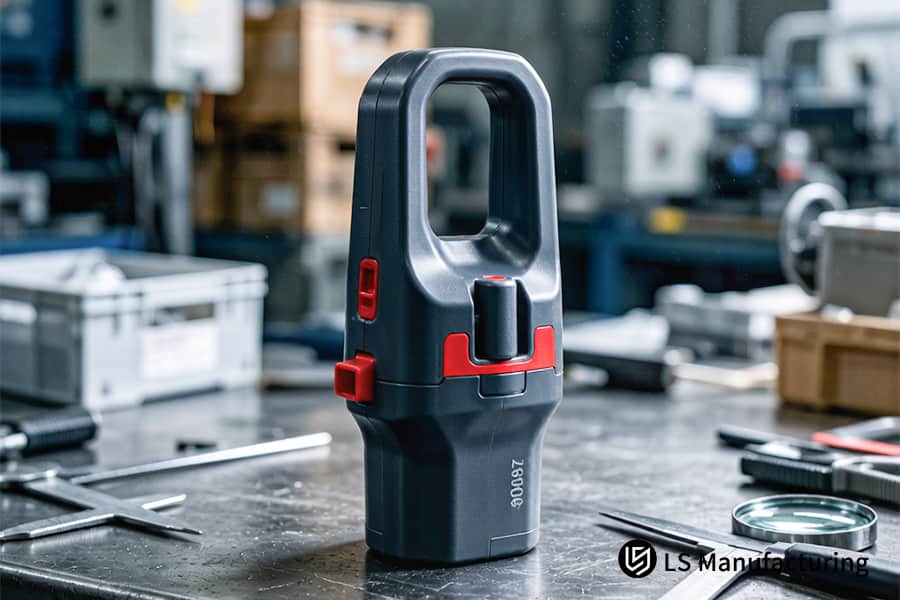
Figure 3: Black overmolded handle grips undergo precision measurement for ergonomic medical equipment tools.
What Strict Quality Control Metrics Define A Medical Grade Overmolding Supplier?
The process for medical grade overmolding calls for a feedback-controlled quality assurance loop that confirms each process parameter. By implementing IQ/OQ/PQ methodology, having 500 Hz continuous screw pressure feedback, and performing the three-factor orthogonal quadratic analysis of pack pressure and hold time, you will have two ways of having zero-defective batches by employing medical grade overmolding quality control. Here is the way in which the following metrics make up a medical grade overmolding supplier:
Quality Control Metrics: Conventional vs ISO 13485-Compliant
| Parameter | Conventional Approach | Strict ISO 13485 Approach |
| Process validation | Partial IQ/OQ, no PQ | Full IQ/OQ/PQ with documented acceptance criteria through overmolding compliance testing |
| Data collection frequency | Manual spot checks (≤1 Hz) | Continual 500 Hz measurements via data logging |
| Process window establishment | Single-point setpoints | 3D quadratic orthogonal design (pack pressure × hold time × temperature) |
| Defect rate target | ≤1% acceptable | ZDL of ≤0.01% defects with statistical proof through overmolding defect prevention |
| Traceability | Lot-level records | Pressure profile traceability at individual parts with serial numbers |
Each row shows a measurable requirement proven during mold qualification. The difference shows that ISO 13485 overmolding manufacturer certificate is based on data-driven process control rather than visual verification.
You get the validated process package with IQ/OQ/PQ validation reports, pressure signatures at 500 Hz for each production shot, and statistical calculation of process window, which does not leave space for any trials. This makes it possible to provide void free medical overmolding quote precision from the first production lot, saving you up to 40% of validation time and bringing the number of audit nonconformities down to zero. For projects demanding surgical precision, these criteria make the basis of the quality management system.
How Can Smart Material Pairing Achieve A Cost Effective Overmolding Vendor Selection?
Choosing the proper material combination saves you money on surface plasma treatment, while increasing the bond strength by 40%. Using the information about medical grade polymers compatibility coefficients – PC/ABS, PEEK, PPSU with TPU/TPE – prevents you from paying an extra $0.35 per part for the surface treatment procedure. Here is how smart pairing achieves a cost effective overmolding vendor:
Compatibility Coefficient Screening
Select the correct combination based on the Hansen solubility parameter and published adhesion results. The coefficient is >0.85 for PC/ABS with TPU, implying high intermolecular bonding without plasma processing. This results in $0.35/part savings ($35,000 for 100,000 parts) while giving a 40% greater peel strength than incompatible materials via overmolding material matching.
Database-Driven Substitution
Substitute the material that does not match the other for improved compatibility—if the coefficient is <0.6 for standard PC and TPU, use PC/PBT as an alternative to improve adhesive compatibility without mold modifications and qualification time reduction of 6 weeks through overmolding polymer selection.
Elimination of Secondary Operations
Proper pairing provides >4.5N/mm strength without any corona or flame surface modification. Insulin pen case study involved a switch from plasma-treated PC to PC/PBT+TPU without plasma processing, resulting in $0.35/part savings and successful 500-cycle sterilization validation. This meets the standards of a medical grade overmolding supplier while demonstrating overmolding cost savings.
Cost-Performance Trade-off Analysis
Compare cost inclusive of material costs, processing, and rejection. While a PEEK-to-TPU combination might incur higher material costs, it eliminates plasma and results in less than 0.2% reject rate, offering 18% savings on total cost than lower cost, incompatible materials. You get a matrix analysis with three different options based on total cost and risk considerations for overmolding vendor evaluation.
Through these four methods of pairing, you transform your process of material selection from being a costly exercise into a strategic advantage. Every material combination is tested based on material compatibility and total cost instead of merely looking at cost savings. This is how a custom medical overmolding service delivers high-performance bonds at the lowest possible unit cost without hidden surface treatment expenses.
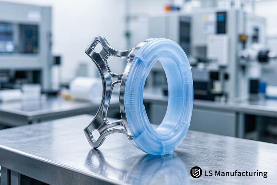
Figure 4: Medical overmolding service creates blue silicone grips on metal inserts for surgical tools.
Why Choose LS Manufacturing For Custom Medical Overmolding Service Projects?
Selecting the right a medical overmolding partner involves identifying risks, getting clean room services, and achieving submicron precision molds, all translating to fast 510(k) certification process. Free design for manufacturability (DFM) by 15-years experienced engineers, ISO-class 100,000 cleanroom services, mold tolerances of ±0.005mm, and Moldflow void prediction form the foundation of the above capabilities. The following is how the above capabilities translate into your competitive edge through our custom medical overmolding service and systematic overmolding engineering analysis:
Free DFM Review by Senior Engineers
- Who reviews: Engineers with over 15-years experience in medical injection molding.
- What you get: Gate, wall thickness, and material suggestions before mold fabrication.
- Risk saved: Reduced cost of $45,000 associated with reworking a 2.5 to 4.0mm step in catheter handle.
This overmolding DFM review catches geometry issues early, preventing costly mold changes.
Class 100,000 Cleanroom Production
- Environment: Precision machining controls cavity dimensions to ±0.005mm.
- Client benefit: Flash-free components in every million cycles, waste minimized below 0.2%.
- Compliance: Medical molds are typically held to ±0.010mm (SPI standard).
This overmolding sterile environment will mitigate contamination risks from the beginning.
Mold Tolerance ±0.005 mm
- Capability: High-precision machining keeps dimensions between ±0.005mm tolerance.
- Client benefit: Flashless overmolded parts with repeatability after millions of cycles (<0.2% scrap rate).
- Comparison: Typical mold tolerance in the industry is ±0.010mm (per SPI specification).
This overmolding dimensional accuracy ensures repeatable bond lines and fit.
Moldflow Void Prediction + PPAP Package
- Simulation: 3D visualization of mold flow and void risk prior to mold construction.
- Deliverable: Comprehensive PPAP including process capability index (CpK≥1.67).
- Client benefit: The 510(k) application will include validation data and save up to 30% of review cycles.
This package is provided by our precision overmolding DFM service with guaranteed first-pass validation.
Free DFM to PPAP—every step will shave off the time to market and any surprises you might have. With 15 years experience, ISO class 8 cleanrooms, ±0.005mm machining, and simulation-driven validation, you get a clear pathway to FDA approval backed by regulatory compliance. This is what it means when you choose a cost effective overmolding vendor.
LS Manufacturing's Custom Solution For PEEK Handles Of Medical Surgical Endoscopes (Two-Color Multi-Layer Injection Molding)
A PEEK endoscope handle with 1.2mm TPU overmold broke down after 35 autoclave cycles at 134°C, displaying a delamination of 0.45mm and internal voids of 0.3 mm in Micro-CT analysis. An almost FDA rejection led to a full process change. Below is an engineering solution for the client problem through overmolding engineering support:
Client Challenge
The previous use of pin gates resulted in shear rates over 75,000 s⁻¹, resulting in jetting and entrapped air to form internal voids of 0.3mm continuously. After being used for 35 times, the moisture penetrated the material due to the presence of a 0.45mm delamination, hence making the component non-sterilizable. The client was facing delays by six months with a possible loss of $2.8M worth of investment.
LS Manufacturing Solution
Moldflow simulation replaced the 0.5mm pin gate with a 0.8mm fan side gate, cutting shear rate by 45% and adding 0.02mm peripheral vents. The PEEK substrate received 0.6mm deep undercuts at 35° draft for mechanical interlocking. Dynamic mold temperature control held the PEEK surface at 145°C ±1.5°C, enabling micron-level remelting and eliminating plasma pretreatment. This overmolding prototype testing validated all three root-cause fixes before production.
Results and Value
The first 500-piece beta run achieved 100% void-free status verified by Micro-CT. Bond strength reached 5.2 N/mm—15% above the 4.5 N/mm industry threshold. The handle passed 150 cycles of 134°C steam sterilization and 50 kGy gamma aging with zero defects. This enabled FDA 510(k) clearance within the original timeline. The successful production scale-up eliminated plasma treatment, reducing per-unit cost by $0.35.
This case proves that systematic DFM—gate optimization, mechanical interlock design, and dynamic thermal control—transforms a failing program into regulatory success. You gain a validated, audit-ready process that passes sterilization on the first attempt, supported by thorough overmolding supplier audit documentation.
Transform your sterilization failure into FDA-ready validation. To bypass costly plasma treatment and secure 150-cycle bond integrity, contact our overmolding engineers for a process review and a per-unit cost quotation.

FAQs
1. What is the primary cause of layer delamination in multi-material medical devices?
The fundamental problem is the incompatibility of the two materials used in overmolding and the insufficient mold temperature during secondary molding. In this case, rapid cooling and low temperatures lead to a lack of diffusion between the molecules at the bonding point.
2. How does LS Manufacturing detect hidden vacuum voids inside custom overmolded parts?
At LS Manufacturing, we use micro-CT scanning and ultrasonic inspection within our Class 100,000 clean room to detect micropores with diameter sizes ≥0.01mm. This ensures that your components are free from any internal defects and in compliance with strict medical device quality requirements.
3. Can we pass ISO 13485 audits if our overmolding supplier uses manual inserts?
There is always a possibility of contamination and temperature variations that may affect the process and its traceability. On the other hand, our supplier LS Manufacturing employs robotics in the six-axis for full automation with in-line monitoring of temperatures, ensuring a complete traceability process as per ISO 13485.
4. What surface roughness specification is recommended for high-strength mechanical bonding?
For maximum mechanical interlocking strength, we recommend setting the EDM texture or machining finish at the bonding interface to VDI 24–VDI 30 (Ra 1.6–3.2 μm). This optimized roughness profile provides sufficient anchor points for the overmolding material without creating stress risers.
5. How do you prevent material degradation when overmolding sensitive medical-grade resins?
We prevent degradation by using Moldflow simulation to limit the shear rate at the screw tip to ≤40,000 s⁻¹ and employing a nitrogen-purged, high-precision heated barrel. This reduces material residence time in the hot runner to under 180 seconds, protecting sensitive polymers from thermal breakdown.
6. What is the typical lead time for a standard medical overmolding service prototype?
Lead time will be between 14 to 21 days for standard medical overmolding after the completion of DFM and design freeze. We use a high-end, totally automated 5-axis machining center for creating molds in record time. Secure your standard medical overmolding prototype in as few as 14 days. To lock in this accelerated timeline for your project, submit your design today for a DFM review and a rapid production quotation.
7. How do thin-walled designs affect void formations in precision medical device manufacturing?
Extremely thin wall designs (≤0.5mm) significantly increase the flow resistance and create a lot of shear heat when filling the mold. Sharp transitions of the wall will result in melt fracture and generation of gas bubbles, leading to micro-vacuum voids within the parts.
8. Why is a fan gate preferred over a pin-point gate for preventing internal voids?
The fan gate allows more space for smoother transitioning of the molten material into the cavity, which helps prevent turbulence (jetting). With a scientifically designed pressure transmission channel, it prevents voids formation through efficient venting of air bubbles.
Summary
Medical-device overmolding demands deep understanding of polymer fluid dynamics and stringent process execution to overcome delamination and voids. Key factors include mechanical undercut interlocking, wall-thickness variation controlled within ±15%, and scientific shear-rate pressure drop in flow channels. LS Manufacturing integrates precise DFM reviews under ISO 13485, using quantified scientific data to eliminate quality uncertainties in mass production.
Reject costly blind trial molding. Facing delamination, porosity, flash, or dimensional instability in multi-material medical devices? Stop futile parameter tuning. Click to get a quote and DFM review; upload your STEP/IGS/X_T CAD files. Within 24 hours, our senior polymer engineers will deliver an in-depth DFM white paper with flow simulation, gate-location optimization, and interlock improvements—safeguarding your innovation with ISO 13485-certified expertise.
📞Tel: +86 185 6675 9667
📧Email: info@lsrpf.com
🌐Website: https://lsrpf.com/
Disclaimer
The contents of this page are for informational purposes only. LS Manufacturing services There are no representations or warranties, express or implied, as to the accuracy, completeness or validity of the information. It should not be inferred that a third-party supplier or manufacturer will provide performance parameters, geometric tolerances, specific design characteristics, material quality and type or workmanship through the LS Manufacturing network. It's the buyer's responsibility. Require parts quotation Identify specific requirements for these sections.Please contact us for more information.
LS Manufacturing Team
LS Manufacturing is an industry-leading company. Focus on custom manufacturing solutions. We have over 20 years of experience with over 5,000 customers, and we focus on high precision CNC machining, Sheet metal manufacturing, 3D printing, Injection molding. Metal stamping,and other one-stop manufacturing services.
Our factory is equipped with over 100 state-of-the-art 5-axis machining centers, ISO 9001:2015 certified. We provide fast, efficient and high-quality manufacturing solutions to customers in more than 150 countries around the world. Whether it is small volume production or large-scale customization, we can meet your needs with the fastest delivery within 24 hours. choose LS Manufacturing. This means selection efficiency, quality and professionalism.
To learn more, visit our website:www.lsrpf.com.