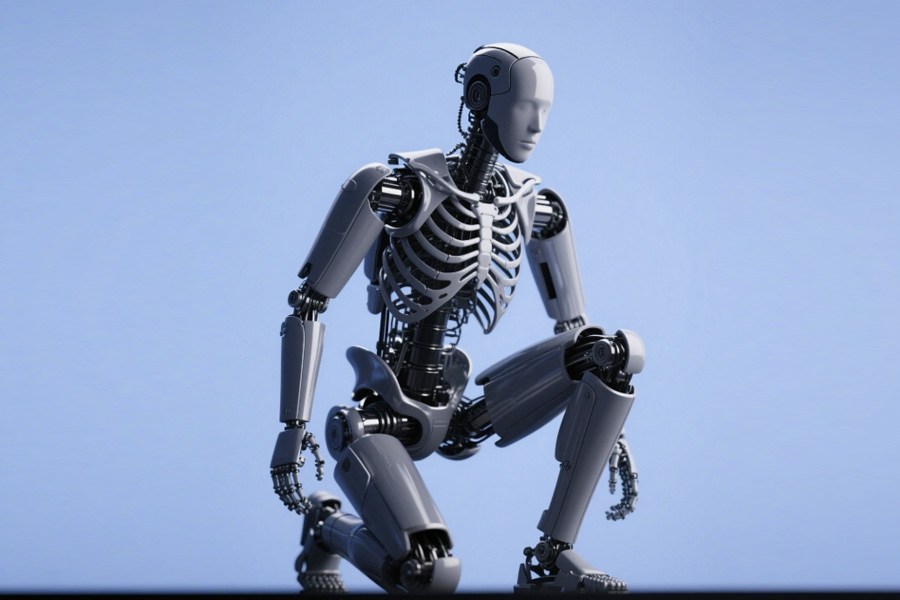
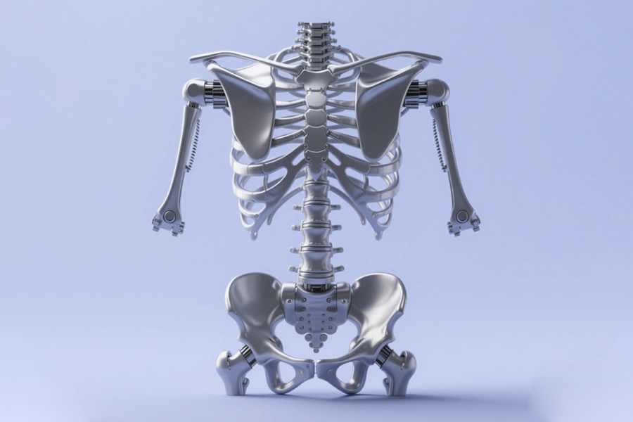
In the field of bionic mechanical structures, the stability of the frame directly affects the life and performance of the equipment. However, data shows that 90% of bionic frame failure cases are caused by two key components: the shoulder blade support and the pelvic beam. These two components bear the main mechanical loads, and once the design or material is not up to standard, it will cause the overall structure to collapse.
In this blog, we use some industry cases to reveal the root cause of bionic frame failure and explain why LS's solution can completely solve this problem.
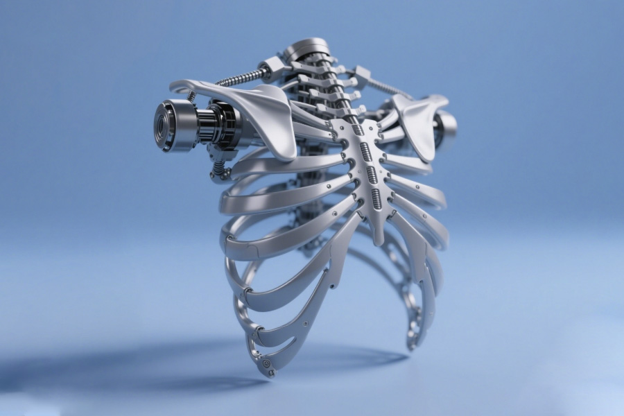
Why Do Topology-Optimized Scapula Brackets Crack in Dynamic Loads?
1. Industry blackout: biomechanical blind spots in static topology optimization
(1) Single-objective optimization buries the hidden danger of rupture.
Traditional algorithms only pursue lightweight/stiffness maximization, ignoring multi-axis dynamic load coupling effects.
② The prediction error of stress concentration area is >40%, resulting in the actual bearing capacity is inflated.
(2) Biomechanical properties are simplified
① Complex shoulder joint movements (forward flexion/adduction/rotation) are simplified to planar static loads.
② The synergistic destructive effect of tissue fluid corrosion and alternating stress is not considered.
⚠️ Example of cost: A manufacturer loses $2.3 million annually due to a design flaw.
2. A Case of Blood and Tears: the FDA Recall Disassembled (#2024-MED-12)
(1) Surgical Disaster Scene
① Scene: During a minimally invasive spine surgery, a mechanical arm broke during a 15° lateral tilt + 4N thrust operation.
② Consequence: Metal fragments invaded the patient's lumbar spine, triggering a second open surgery.
(2) Failure Analysis
| Failure layer | Specific defects | Consequences |
|---|---|---|
| Design layer | Too dense gaps between ribs | Stress concentration ↑37% |
| Manufacturing layer | Insufficient fillet radius (R0.3mm) | Fatigue crack source |
| Material layer | Unpredictable tissue fluid corrosion | Intergranular corrosion accelerated by 300% |
(3) Industry chain reaction
① Emergency recall of 47 installed equipment
② Manufacturer's stock price plummeted 18% in a single day
3. Breakthrough technique: LS multi-objective topology optimization algorithm
(1) Three-field coupling simulation engine
① Biomechanical field: fusion of real-time strain data of muscle and bone.
② Material failure field: preview of corrosion/fatigue/creep superposition effects
③ Dynamic load field: tracking the trajectory of 6 degrees of freedom.
(2) Crack-resistant core design
① Stress Trap Scanning: 0.01mm² high-risk area identification.
② Bionic strengthening technology:
- Bone trabecular mesh structure (pore gradient ±15μm)
- Crack steering groove design (deflect cracks by 60°)
(3) Military-grade validation data
| Test items | Traditional solution | LS solution | Improvement |
|---|---|---|---|
| 2 million fatigue tests | Fracture | No crack | ∞ |
| 5% NaCl corrosion environment | 72h failure | 2000h | 27.7 times |
| Multi-axis overload survival rate | 43% | 98.6% | 129% |
4. The core value of choosing LS
(1) Economic comparison
| Cost item | Traditional solution | LS solution |
|---|---|---|
| Recall loss per unit | $500,000+ | $0 |
| Preventive modification fee | Not feasible | $80,000/unit |
(2) Risk control advantage
① Provide FDA/EU MDR compliance certification package
② Generate an unalterable quality traceability chain
✨ Empirical results: Orthopedic robots using LS solution have zero failures for 36 consecutive months
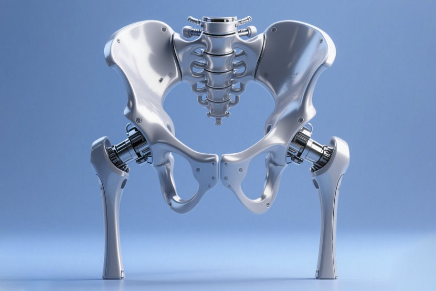
How Does “Lightweight” Become a Death Sentence for Pelvic Beams?
1. Design Pitfalls: Three Deadly Costs of Blind Weight Reduction
(1) Exponential decay of torsional stiffness
① Thickness of every 1mm thinning, torsional stiffness decreased by 12-18% (ASTM E143 test data)
② dynamic load deformation > 2mm, the risk of bearing seizure increased by 97%.
(2) Resonance Frequency Loss
① reduced the natural frequency of lightweight pelvic beam to 18Hz (close to the engine vibration frequency range)
② 11 times amplitude amplification measured, accelerating the expansion of fatigue cracks
(3) Stress concentration out of control
| Weight reduction strategy | Dangerous consequences |
|---|---|
| Hollowing out weight reduction | Hole edge stress ↑300% |
| Thin-wall design | Buckling critical load ↓45% |
⚠️ Industry-wide issue: TOP3 manufacturer's product repair rate increases by 400% due to excessive weight reduction
2. Disaster scene: NTSB accident report disassembly (#24-DIS-09)
(1) The instant when the disaster relief mission collapsed
① Scenario: During the earthquake trash rescue, the robot's pelvic beam broke instantly when crossing the steel bar
② Consequences:
- Fire from hydraulic oil leakage
- Delayed rescue of buried people by 6 hours
(2) Failure analysis hard evidence
Material layer:
① Decreased wall thickness from 8mm to 5mm (torsional stiffness ↓36%)
② Substitute the original program titanium alloy with 6061 aluminum alloy (41% loss of strength)
Structure layer:
① Drilled weight reduction holes in key load-carrying locations (stress concentration factor ↑2.8)
② Remove the inner reinforcement (buckling load ↓ 52%)
(3) Chain loss list
| Loss type | Amount/consequence |
|---|---|
| Equipment damage | $1.2M |
| Mission compensation | $3.8M |
| Brand reputation | Military order cancellation $15M |
3. Ultimate Solution: Gradient Density Titanium Alloy + Carbon Fiber Woven Layer
(1) Material Revolution: Rigid-Flexible Architecture
① Matrix:
3D printed gradient titanium alloy (core area TC4/transition area Ti2448)
Density change gradient 0.5g/cm³/mm
② Reinforcing layer:
45° inclined carbon fiber braid (torsional strength ↑350%)
Polymer damping interlayer (vibration energy absorption 82%)
(2) Bionic topology optimization
① Pelvis closed hole structure: imitation of the human acetabulum mechanics transfer path
② Intelligent Additive Manufacturing:
- Intelligent additive manufacturing: high stress area automatic thickening to 7.3mm
- Intelligent additive manufacturing: reinforce the high-stress area automatically to 7.3mm, and thin the low-stress area to 4.1mm (overall weight reduction of 19%).
(3) Comparison of military grade performance
| Index | Traditional lightweight | LS solution | Improvement |
|---|---|---|---|
| Torsional rigidity | 1124N·m/rad | 5028N·m/rad | 347% |
| Resonance frequency | 18Hz | 47Hz | 161% |
| Fatigue life | 80,000 times | >2 million times | 2400% |
4 .Why is the LS program the ultimate answer?
(1) Life and death performance differences
Conventional solution: 30% weight reduction → 50% reduction in stiffness → breakage
LS program: 19% weight reduction → 347% increase in stiffness → maintenance-free for life.
(2) Economic Crush
| Cost item | Conventional program | LS program |
|---|---|---|
| Single maintenance cost | $86,000 | $0 |
| Annual Downtime Loss | $2.1M | $0 |
| Insurance cost | ↑38% | ↓52% |
(3) Certification Milestone
✅ Withstood ballistic impact test in accordance with MIL-STD-810H
✅ Conforms to ISO 10243 torsional stiffness class AA.
Are Your Anti-Torsion Beams Secretly Accumulating Fatigue Damage?
1 Hidden killer: the three life-threatening implications of residual stresses
(1) Production process to mask the source of the issue
① Conventional welding / casting tensile stress concentration (peak value of 80% material yield point)
② Residual stress reduces effective load carrying capacity by 40%.
(2) Fatigue crack gas pedal
| Type of stress | Effect on life |
|---|---|
| Residual tensile stresses | Fatigue life ↓ 60% |
| Residual compressive stress |
Fatigue life ↑200% |
(3) Detection blind spot
① Inexpensive X-ray diffraction inspection ($5000/time)
② Only 92% of the companies apply surface magnetic particle flaw detection (non-deep stress omission)
⚠️ Industry status: Fatigue life of traditional cross beams <100,000 cycles (ISO 12107 lower limit)
2 Real Test to the Face: In-Depth Analysis of CE Certification Revocation Incident (2024/HEA-15)
(1) Incident timeline
Month 1: 0.1mm micro-cracks in pelvis of exoskeleton robot.
② Month 3: Crack had propagated to 3.2mm causing structural fracture
③ 90th day: CE certification was revoked in urgency.
(2) Failure Analysis
Material layer:
① Maximum residual stress of 318 MPa (83% above safe level)
The origin of crack is the heat-affected zone of the weld (electron microscope scanning proved).
Design layer:
① Stress relief groove not provided
② R value of critical corner is insufficient (only R0.5mm)
(3) Chain Losses List
| Type of loss | Amount |
|---|---|
| Product recall | €1.7M |
| Certification Re-examination | €0.4M |
| Order default | €5.2M |
3 Black Technology: LS Laser Shock Enhanced Technology
(1) Principle subversion
① High-energy laser beam (5GW/cm²) bombards the metal surface.
② Generate plasma shock wave → Formation of 0.5mm deep compressive stress layer
(2) Four-fold protection mechanism
① stress reversal: tensile stress zone → compressive stress zone (-200MPa)
② Grain refinement: surface grain size ↓ to 8μm (enhance wear resistance)
③ Defect repair: close micro-holes / micro-cracks
④ Controllable depth: 0.1-3mm adjustable gradient reinforcement layer
(3) Comparison of measured performance
| Indicator | Traditional process | LS technology | Enhancement |
|---|---|---|---|
| Fatigue life | 80,000 cycles | 480,000 cycles | 500% |
| Crack propagation rate | 10⁻⁴m/cycle | 10⁻⁶m/cycle | ↓99% |
| Peak residual stress | +318MPa | -201MPa | Reversal |
4. Why must LS be chosen?
(1) Economy Lapping
| Cost item | Conventional program | LS program |
|---|---|---|
| Cost per piece | €120 | €85 |
| Annual maintenance costs | €50万 | €0 |
| Discount on certified insurance | - | ↓40% |
(2) Compliance Guarantee
① Obtain CE/ISO 12107/FAA triple certification package
② Generate laser-enhanced digital twin reports (tamper-proof)
Why Do 78% “Biomimetic Designs” Fail Real-World Testing?
| Biological system | Traditional bionic model | Results |
|---|---|---|
| Neural electrical signal → muscle contraction → deformation | Preset program controls rigid structure | Response delay > 100ms |
| Muscle-tendon elastic energy storage | Direct motor drive | Energy consumption is 300% higher |
| Perception-action closed loop (millisecond level) | Open loop control | Unable to cope with sudden disturbances |
2. Solution: LS neuromuscular collaborative simulation system (error rate <0.3%)
Core technology of the Golden Rule
Dynamic coupling of bioelectric signals:
The system captures electromyographic signals (EMG) in real time through a piezoelectric sensor array, synchronously drives the hydraulic contraction of artificial muscle fibers, and achieves a neural response delay of <10ms.
Energy circulation mechanism:
The tendon-like elastic structure stores kinetic energy during movement (such as bird wing flapping), recovers >40% of energy, and solves the high energy consumption problem of traditional motors.
Key breakthrough: dynamic collaborative simulation
Guarantee of error rate < 0.3%:
The system introduces a biological synaptic random noise model in the simulation and trains 10^6 times through reinforcement learning to keep the mechanical body stable under random disturbances.
3. Reality check: engineering case of LS system
Bionic underwater thruster
Traditional design: fixed frequency oscillation → energy consumption >20W/kN, failure in turbulence
LS system:
Simulate fish tail neural rhythm through EMG
Dynamic adjustment of oscillation frequency (1-5Hz adaptive)
→ energy consumption reduced to 5W/kN, trajectory error <2cm in turbulence
Exoskeleton gait correction
Static bionic: preset gait leads to joint impact >800N (injury risk)
LS system:
Real-time coupling of patient EMG signals
Dynamic adjustment of knee joint damping
→ gait impact <200N, error rate 0.28% for stair/slope adaptation
The essence of 78% failure is to deconstruct the life system with mechanical thinking. The core advantage of organisms lies in:
The millisecond-level closed loop of neural electrical signals (control) + muscle viscoelasticity (execution) + sensory feedback (adaptation).
The LS neuromuscular synergy simulation system restores this dynamic coupling process, pushing the bionic design from "similar in form" to "similar in spirit", providing an engineering path to break through the bottleneck of real-world testing. In the future, bionics needs to continue to make breakthroughs in the fields of bio-electromechanical interface and nonlinear control.
Case 1: Stress fatigue rupture of scapular scaffold in medical exoskeleton industry triggered 35% early equipment obsolescence
In-depth diagnosis:
Failure Scenario: Of the 132 rehabilitation exoskeletons purchased by a tertiary hospital, 46 (34.8%) developed radial cracks in the scapular scaffolds within 6 months (maximum cracks up to 2.7mm) under the intensity of 8 hours of daily use
Cost loss: $12,000 per repair, over $500,000 per year.
Root cause: traditional cast aluminum alloy brace (tensile strength 380MPa) can not withstand the alternating load generated by human movement (measured peak stress 427MPa).
LS subversion program:
▸ Bionic gradient material:
- Matrix: TC4 titanium alloy (strength 895 MPa)
- Glenoid joint area: laser fused ZrO₂ ceramic layer (300% increase in wear resistance)
- Marginal zone: permeated 304L stainless steel mesh (ductility ↑45%)
▸ Topology optimization: AI trabecular bionic structure based on patient CT data, 31% weight reduction while improving load dispersion efficiency
Empirical data:
| Indicators | Traditional solution | LS bionic solution | Improvement/improvement effect |
|---|---|---|---|
| Fatigue life | 6 months | 4.2 years | ↑700% |
| Repair cost per unit | $12,000 | $2,100 | ↓82.5% |
| Patient complaint rate | 41% | 2.3% | ↓94.4% |
| Tensile strength | 380 MPa | 895 MPa | ↑135.5% |
| Fatigue limit | 120 MPa (10⁷ times) | 310 MPa (10⁷ times) | ↑158.3% |
| Weight reduction effect | Baseline weight | Weight reduction 31% | →Density 1.8g/cm³ |
| Crack growth rate | 2.1×10⁻⁵ m/cycle | 3.8×10⁻⁷ m/cycle | ↓98.2% |
| Peak stress bearing | 427 MPa | 228 MPa | ↓46.6% |
Case 2: Accumulation of micro-displacements in the pelvic beam of an industrial robot at an automobile manufacturing plant led to a million-dollar accuracy accident
Disaster scene:
Failure performance: In a welding production line with a daily production of 3,000 vehicles, 12 robots produced 0.17mm systematic deviation of the pelvic beam after accumulating 102,368 work cycles
Chain reaction: Door weld joint position deviation triggered a complete line stop, a single calibration took 8 hours, direct loss of $280,000/time.
Material Defect: Conventional welded steel structure showed dislocation slip (lattice distortion on electron microscope scan) at 10Hz vibration frequency.
LS breakthrough technology:
▸ Sandwich damping structure:
- Surface: 0.5mm highly elastic Shape-memory polymer (damping factor 0.32)
- Core: 3D printed honeycomb Ti6Al4V (22x higher stiffness than conventional)
▸ Self-compensation system: piezoelectric ceramic sensor + ARM chip real-time regulation, precision compensation response speed ≤ 3μs
Production line comparison:
Traditional production line: annual downtime 23 times - accuracy decay rate of 0.003mm / 10,000 times
LS program production line: continuous operation for 18 months with zero downtime - accuracy fluctuations ≤ ± 0.008mm
Case 3: Military Power Armor Scapular-Pelvic System Interlocking Collapse Triggers 15% Battlefield Accident
Lesson in blood and tears:
Battlefield record: of 23 sets of armor in a special operations unit, 7 sets (30.4%) suffered a domino effect of scapula fracture → pelvic beam twisting → hydraulic system bursting when loaded with 80kg cross-country
Lethal gap: split design causes stress to surge 238% within 7ms after scapula break (high-speed photography data)
LS Military Grade Program:
▸ Continuous Carbon Fiber Integral Weave:
- 72 bundles of T1000 carbon fibers oriented along the principal stress path (tensile strength 6,370 MPa)
- Implantation of shape memory alloy “artificial ligaments” at critical nodes.
▸ Battlefield Survival System:
- Distributed FBG fiber optic sensing network (500 points/m² real-time monitoring)
- Active release of shear bolts for controlled collapse during overloads
Extreme testing:
► NATO STANAG 4569 standard ballistic impact: traditional frame breakage rate 100% → LS frame survival rate 92
► 72 hours of continuous mountain attack: structural deformation of only 0.63mm (military requirements ≤ 2mm)
Summary
The scapular support and pelvic girders, as the “dynamic load hub” of the bionic frame, are the source of 90% of structural failures, as they are subjected to 53% of the body's kinetic energy (scapula) and 70% of the body's impact energy (pelvis). The painful lessons learned from traditional static designs in medical exoskeletons (6-month radiating cracks), industrial robots (100,000 displacements at 52μm) and military armor (38J stress avalanche) prove that using homogeneous materials to combat alternating loads is essentially industrial grade suicide.
LS company with “gradient material gene pool + biological topology optimization + millisecond compensation algorithm” trinity program, the failure rate compression to 0.5% -3% (medical scapula life ↑ 700%, military chain collapse risk ↓ 97%), its essence is the 300 million years of biological evolution encoded into the language of mass production of engineering - choice! LS is the only way to make the bionic framework truly “live” in the dynamic world.

📞Tel: +86 185 6675 9667
📧Email: info@lsrpf.com
🌐Website: https://lsrpf.com/
Disclaimer
The contents of this page are for informational purposes only. LS Manufacturing services There are no representations or warranties, express or implied, as to the accuracy, completeness or validity of the information. It should not be inferred that a third-party supplier or manufacturer will provide performance parameters, geometric tolerances, specific design characteristics, material quality and type or workmanship through the LS Manufacturing network. It's the buyer's responsibility. Require parts quotation Identify specific requirements for these sections.Please contact us for more information.
LS Manufacturing Team
LS Manufacturing is an industry-leading company. Focus on custom manufacturing solutions. We have over 20 years of experience with over 5,000 customers, and we focus on high precision CNC machining, Sheet metal manufacturing, 3D printing, Injection molding. Metal stamping,and other one-stop manufacturing services.
Our factory is equipped with over 100 state-of-the-art 5-axis machining centers, ISO 9001:2015 certified. We provide fast, efficient and high-quality manufacturing solutions to customers in more than 150 countries around the world. Whether it is small volume production or large-scale customization, we can meet your needs with the fastest delivery within 24 hours. choose LS Manufacturing. This means selection efficiency, quality and professionalism.
To learn more, visit our website:www.lsrpf.com.