Precision machining services face critical problems in thread manufacturing, such as tap breakage, quality variability, and inefficiency. The traditional way of tool choice will increase variability in tool life by 300% and variability in machining cost by 25% at least. Precision machining services face critical problems in thread manufacturing, tap breakage, quality variability, and inefficiency.
This approach makes possible data-driven solutions based on the tapping science that has been developed using a compendium of more than 2,000 threading situations collected by LS Manufacturing. This streamlines the toolkit configuration with materials and cutting data with the objective of maximizing machining efficiency by 30% while minimizing tooling costs by 40%.
Thread Taps: Performance & Cost Optimization Quick-Reference Guide
| Section | Key Points |
| Basics & Types | Description of taps, their usage. Types of taps: Hand taps, Machine taps, Pipe taps, Forming taps. |
| Selection Criteria | Factors: Material, Hole specifications, Thread types, Desired finish, Machine compatibility. |
| Coatings & Materials | Common options: HSS, carbide. Coatings: TiN, TiCN, TiAlN for life/speed. |
| Performance Tips | Correct speeds/feeds, lubrication, correct setup, peck tapping for difficult-to-cut materials. |
| Cost Optimization | Right tap installed, preventive maintenance, batching, supplier partnerships. |
| Problem Solving | Guides for common issues: breakage, poor threads, wear, chatter. |
This technical guide is filled with valuable know-how on the selection, application, and care of thread tapping equipment. Our company offers helpful support for our valued clients on pressing matters like keeping tool breakage at bay and extending tool life cycles, especially regarding relatively affordable hole drilling procedures.
Why Trust This Guide? Practical Experience From LS Manufacturing Experts
Talking about the precision machining services and, specifically, the production of thread taps, the degree of our knowledge gained results from practice. We have already solved the most essential tasks in the aerospace industry, the medical industry, and the automobile industry. Each piece of knowledge stated within the manual rests on practice.
Our methodology is dealing with severe requirements, like those from the ASTM International and the Aluminium Association (AAC), while we are going to make the best possible choice regarding the tap material as well as the parameters of cutting, with a view to achieve the best possible performance as well as the best possible accuracy.
And not to mention ensuring you are guaranteed quality and cost-effectiveness in helping you get the best out of precision machining. Utilizing expert knowledge and best practices within the trade, we use this guide to equip you with strategies on effective tapping of threads, ensuring optimal outcomes are also guaranteed within its guarantee.
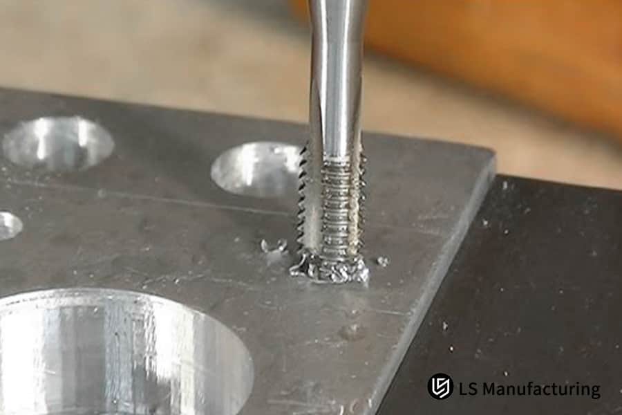
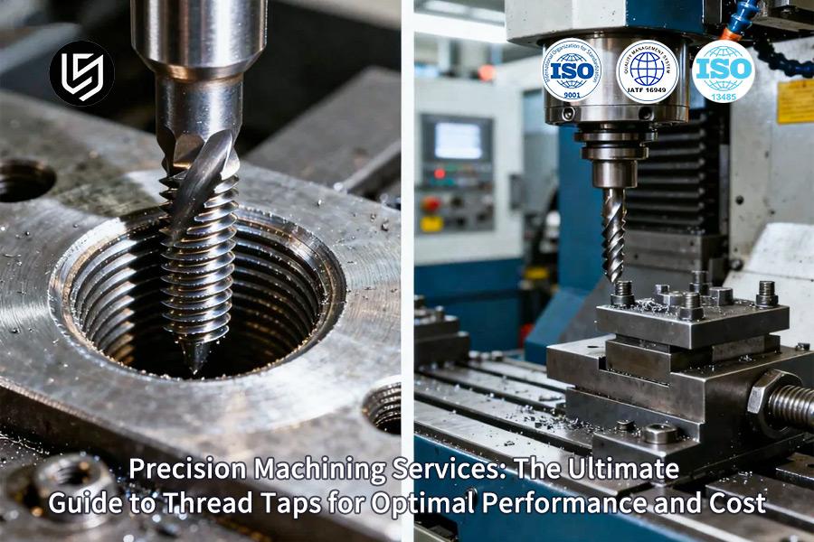
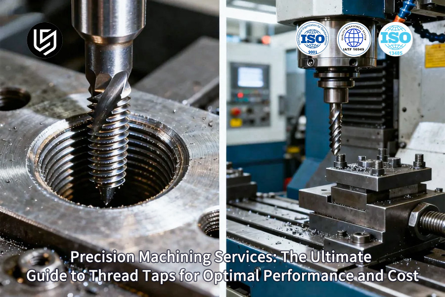
Figure 1: Selecting the right thread taps for precision machining by LS Manufacturing
How Can Precision Machining Services Improve Thread Machining Efficiency And Quality?
The unscientific tool choice thus leads to tool breakage, wear and tear at the wrong time, and thread quality variation. A cost-effective thread tapping needs a predictive and scientific tool choice technique in high-mix production. This can be achieved by: the four-step process:
- Taming Gummy Materials with Optimized Geometry: Materials such as 316 stainless steel have the property of work-hardening that makes the generation of chips long and fibrous. In this case, we make use of the advantage of the design of the taps that have a TiCN finish. This allows a stable 15-20 m/min cutting speed, maintaining thread tap performance and preventing catastrophic tool failure.
- Mitigating Abrasion in Brittle Alloys: The powder produced is highly abrasive. Gray cast iron material gives us a very abrasive powder. Our taps are straight-flute taps and have an oxidation finish. This improves evacuation of powder. The oxidation finish makes the wear resistance better because the finish protects against wear from powder due to its hardness. Wear is controlled at 10-15 m/min.
- Preventing Adhesion in Non-Ferrous Applications: It is prone to galling on aluminum alloys. This gives rise to poor finish surfaces and coarse threads. This requires the application of point-style or spiral-point taps with TiN finish. For this type of taps, the chip removal takes place ahead of the point. This enables the machining process to be performed with high-speed machines, with speeds ranging from 30 to 50 meter/minute.
- Implementing a Proprietary Selection Database: We translate this material-specific logic into a reliable standard operating procedure.Our proprietary selection database correlates material grade, hardness, and hole conditions with validated tool specifications to eliminate the guesswork and assure repeatable thread tap performance across shifts. Thread tapping is one of the cornerstones of providing reliable precision machining services.
It is replicable engineering documentation in tap selection, not general catalog data, that shows exactly how specific-and costly-production challenges can be resolved through targeted tool and parameter selection. This actionable technical depth characterizes expert-level precision machining services.

How To Select The Most Suitable Thread Tap Type Based On The Workpiece Material?
Achieving maximum tool life and cost efficiency in threading operations hinges on the optimal thread tap selection. However, the main challenge in determining how to choose thread taps lies in aligning their characteristics with the machinability difficulties inherent in the material of the workpiece. This report presents a basis of selection for the thread taps supported by data analysis.
| Workpiece Material | Primary Machining Challenge | Recommended Thread Tap Type | Key Parameter | Documented Result |
| Quenched & Tempered Steel (HRC 30-35) | High Abrasive Wear | Powder High-Speed Steel (HSS-PM) | 8°-10° Rake Angle | Life increased to 800 holes (from 200) |
| Austenitic Stainless Steel (304/316) | Work Hardening, Chip Adhesion | Cobalt High-Speed Steel (HSS-E) | 35° Helix Angle | Reliable chip evacuation achieved |
| Nickel-Based Superalloy (Inconel 718) | High Strength at Temperature | Solid Carbide Tap | 5-8 m/min Cutting Speed | Enabled stable thread production |
How to choose thread taps should be done based on an analytical approach. First, analyze the main machining problem of your material. Based on your result, you can select the thread tap types that matches your need from this table below. This systematic approach will ensure the optimal thread tap selection.
A Comparative Analysis Of Different Threading Taps In Specific Machining Scenarios?
Based on machining applications, there may be several thread tap types also have some characteristics that are critical for proper production to take place. Among the prime objectives of the research study is carrying out a measurable comparison of the different types of CNC thread tapping tools in their optimal form, and the relationship that can exist between the geometric shape and the results.
| Thread Tap Type | Optimal Application Scenario | Key Performance Attribute | Quantified Benefit |
| Spiral Flute Tap (15°-45° helix) | Blind Hole Tapping | Superior Chip Evacuation | Chip removal efficiency increased by 80% |
| Spiral Point Tap (Pointe) | Through Hole Tapping | Efficient Chip Ejection | Processing efficiency improved by 50% |
| Roll Forming Tap (Thread Rolling) | Ductile Materials | Chip-less Process, Work Hardening | Thread strength increased by 30% |
| Spiral Flute Tap (M6x1 Example) | General Blind Hole | Tool Life in Steel |
Life of 3000 holes (compared to 1200 for straight flute) |
To optimize thread tap performance, first define the hole type (blind/through) and material. For blind holes, select a spiral flute tap; for through holes, a spiral point tap. For ductile materials requiring high-strength threads, use a roll forming tap. This application-specific selection, validated by the data above, is essential for achieving superior results in high-value CNC thread tapping operations.
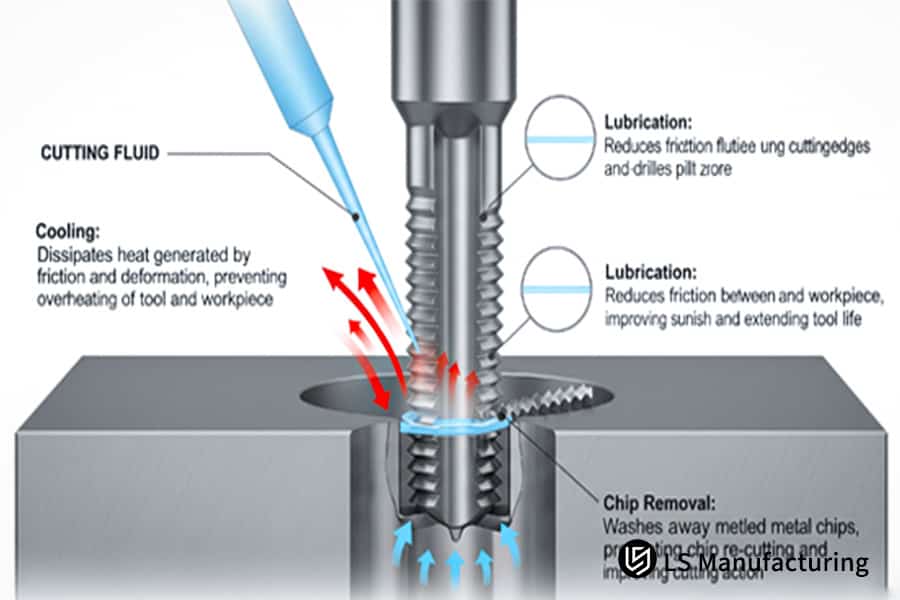
Figure 2: Key roles of coolant in effective thread tapping processes by LS Manufacturing
How To Achieve Cost-Effective Thread Tapping Without Sacrificing Machining Quality?
What this means is that true cost-effective thread tapping is neither gained by using more economical tools nor by a process which is less predictable: in place of adopting less costly tools as a solution to cost-effective thread tapping, a predictable process with a stable thread tapping process with a predictable result is needed. This entails commencing the process of eliminating uncontrolled variables:
Optimizing Feed for Reduced Tool Stress
Overt feeding results in overload cutting, while under-feeding results in a high friction process, which produces high heat. The above is accomplished in the following ways: By presetting the feedrate to 95% of the thread pitch, for example, 1.19mm of thread when using M8x1.25. This controlled engagement directly enhances thread tap performance and forms clean, full-form threads consistently.
Implementing Precise Minimum Quantity Lubrication
One of the most important difficulties in the process of thread tapping is that it is not easy for the flood coolant to reach the cutting region in the case of deep or blind holes. This may result in a thermal shock, along with an adhesive wear. The targeted MQL system with the right amount of lubricate, ranging from 50-100ml/hr, reduces the friction value at the chip-tool interface by making an average micro-film, resulting in an averaged built-up edge with an expectable lifetime for the tool, which is highly essential for the cost-effective thread tapping.
Proactive Monitoring to Eliminate Surprise Failures
Tap breaking can cause costly downtime, material waste, and potential product defects when it suddenly occurs. We also integrate monitoring elements that can measure spindle loading and torque in real time. With a predetermined level for comparison, there can also be an early warning signal for either tool wear or tool alignment. Unplanned downtime can be avoided, as well as material scrapped because of process defects.
This document offers a design strategy with the aim of moving away from the tool replacement thought process that the industry was practicing reactively to now managing by the data process. Various approaches to better the thread tap performance are included within this document, which is the actual key to making the cost-effective thread tapping for the company that delivers precision machining services.
How To Optimize Threading Process Parameters In CNC Machining To Improve Efficiency?
Inappropriate parameters in thread tapping for the CNC process cause either low speed in the process, low life for the tool, or a combination of the two, along with poor thread quality. However, the most challenging operation in this case is often controlling the speed of the spindle together with the Z-axis movement. The process below makes it possible to control these factors:
Implementing Rigid Tapping with Synchronized Control
To avoid deviations of the pitch because of flexible tension-compression holders, for the rigid tapping cycles G84 of the spindle and feed axis with electronic synchronization, we avoid the use of a floating holder since it is ensured that the feed rate is equal to the spindle rotation speed of 1.25mm per revolution. This is particularly important as regards the CNC thread tapping since it is imperative in ensuring the adherence to grade 6H of the precision of the threads in eliminating the least possibility of cross-threads being created.
Calibrating Speed and Feed for Material-Specific Cutting
Even though there may be situations where the general cutting speed and feed rates result in too much heat generation and/or poor chip formation, these values are experimentally proved. This is because, when 1045 steel is worked upon, a cutting speed of 25m/min, which is roughly 800 RPM for M10, along with a feed tolerance of ± 0.02mm is considered. This optimal thread tap selection of parameters balances chip load and heat generation, directly optimizing tool life and enabling a 40% reduction in cycle time.
Utilizing Peck Tapping for Deep-Hole Chip Evacuation
Beyond 2x the diameter of blind hole drilling, the tighter cutting generates higher torque and breakage. To overcome this issue, a program involving a peck tapping cycle subroutine must be established (G84 with Q-value). The drill advances, withdrawing 0.5mm each time, for the removal of the cutting chips. This proactive chip management prevents recutting, reduces tap stress, and is critical for maintaining thread tap performance in challenging applications, extending tool life to over 4000 holes.
This document provides a precise, actionable framework for parameter optimization, moving beyond standard G-code commands. It details the specific how of synchronizing machine functions and selecting data-driven parameters to solve the core challenges of CNC thread tapping, delivering both superior thread tap performance and operational efficiency for high-volume production.
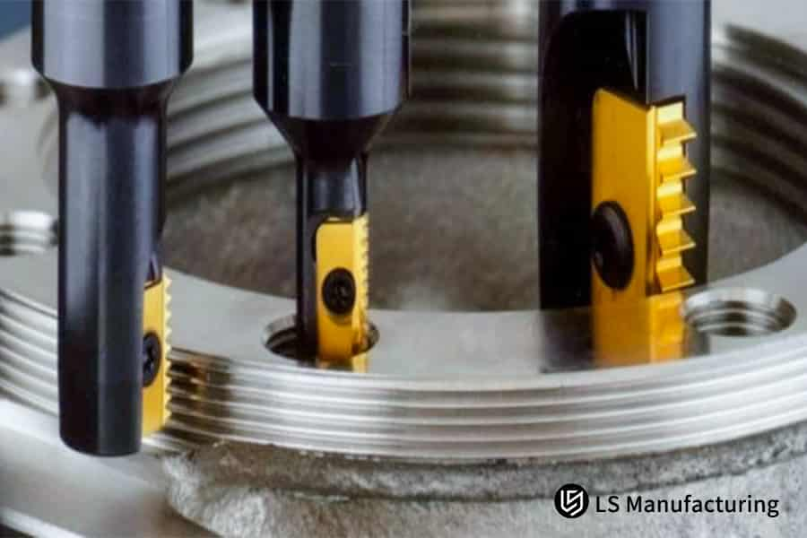
Figure 3: Choosing correct taps for high-precision machining operations by LS Manufacturing
How Can Perfect Tapping Be Achieved Through Optimization Of Tap Geometric Parameters?
Generic thread tapping has low surface finish coupled with high torque values and low tool life. However, the problem with the process is the modification of the angles of cut along with flute design according to the material properties concerning chip formation, adhesion and strength parameters. The approach consists of a precision method having geometric parameters:
- Reducing Cutting Forces in Ductile, Soft Materials: 6061 aluminum alloys, as well as other materials, tend to develop a built-up edge. Additionally, low cutting pressure is recommended. High rake angle taps with 12°-15° angles will be recommended. This configuration helps to sharpen the cutting edge, resulting in shearing the material effectively with less pressure, thereby obtaining thin and easily handleable chips. This process, referred to above regarding the cutting process, reduces the torque by more than 25%. This process also achieves the surface finish with an Ra value below 1.6µm. This is one of the criteria for the quality precision machining services.
- Maintaining Edge Integrity in Abrasive, Tough Alloys: Austenitic stainless steels have the ability to work-harden, as well as be abrasive. A rake angle that is high would tend to chip. Our process employs a higher rake angle of 6° to 8°. This enables the development of a harder cutting edge, able to better resist the high shear strength and hardness of the material. The stronger edge resists deformation, maintaining thread form accuracy over extended tool life and preventing catastrophic failure mid-production, which is essential for reliable thread tap performance.
- Ensuring Chip Evacuation in Gummy, Adhesive Materials: These alloy systems possess high toughness, continuous chips, which can readily be welded to the tool. We employ taps with a variable helix angle of 35-45°. In our design, the increments of the spiral angle lead to a positive rake angle of the flute, intended to aggressively push forward the chips ahead of the tool. This prevents chip packing and galling, the primary causes of tap seizure in titanium, solving a fundamental challenge in how to choose thread taps for reactive metals.
Within this manual, we have described how specific geometric relationships were directly connected to resolving problems with product manufacturing, and in this manual, the discussion will advance upon product recommendation by assisting in the vision of engineers in how geometric choice can be reasonably connected to reliable quality performance, and it is at this level of specific know-how that master professionals in precision machining services are distinguished.
What Are Some Common Solutions To Quality Problems In Precision Thread Machining?
Precision threading problems like deviations in pitch diameter, surface finish, and tearing of threads can themselves affect the fit, function, and assembly. The problems usually arise with the interaction of the tool, parameters, and coolants. The following is a step-by-step solution that focuses on the cause of the problem in every failure mode.
Correcting Pitch Diameter Deviation Through Tap Tolerance Control
Uncontrolled pitch diameter leads to improper bolt fit or poor sealing. The solution is to specify and use taps with a tighter, application-specific tolerance class. For a 6H fit, selecting a tap with a controlled manufacturing tolerance of ±0.01mm on the pitch diameter ensures the cut thread remains within the strict 6H envelope. This proactive CNC thread tapping strategy replaces post-process inspection with in-process guarantee, elevating first-pass yield.
Eliminating Rough Surface Finish with Optimized Cutting Speed
Ra exceeds 3.2µm, creating high friction and likely initiating fatigue cracks due to inappropriate cutting speed, causing excessive heat generation and built-up edge. This is resolved by adjusting the appropriate range of cutting speed for the work material in question. That optimal cutting speed results in shiny and continuous chip formation leading to material shearing without leaving any finish in excess of Ra1.6µm. This is the essence of high-quality precision machining services.
Preventing Thread Tearing via Coolant Concentration Management
Torn threads with a ragged crest are normally due to chip welding and insufficient lubrication on the cutting edges. The coolant alone is not enough; concentration is the name of the game. We employ a controlled method of mixing and testing to ensure that the concentration of solvent oil reaches 8-10%, which will provide a ratio of mixing for maximum lubrication and cooling effect on the cutting edges, making them impervious to material sticking and thus protecting thread tap performance.
One-stop repair suggestions given in this report are particular, corrective solutions, unlike the general process of problem-solving in threads. Each correction not only addresses the process change in tolerance, processing parameter, or fluid control that eliminates the expensive problem of poor quality but also satisfies the required technical know-how of precision machining services.
How To Evaluate The Technical Capabilities And Service Capabilities Of A Thread Tap Supplier?
Reliance on price or availability of thread taps from a supplier may manifest unseen costs on tool life or production time or scattered data points on quality acceptance. Testing of a supplier would involve more than just technical specifications on a thread tap but would consider factors such as ability to work together on resolution of issues related to application. The factors to consider would include:
Assessing Custom Engineering and Design Collaboration Capability
The capability of this supplier, which has only standard tools, cannot cater to special material and geometry-related issues. Evaluate their competence regarding the supply of custom geometry, with modifications in rake angles and flute patterns, required for a particular alloy material. This proactive design support is essential for optimal thread tap selection in non-standard applications, demonstrating a partnership that moves beyond transactional supply to engineered solutions for complex precision machining services.
Quantifying Tool Life Consistency and Value Recovery Options
A guaranteed minimum life of the tool, for instance, at least 3000 holes for HSS taps under given circumstances, ensures cost per hole data for deliberate budgeting. Also, check if they have certified re-grinding facilities for their tools. A supplier who can expertly re-condition their tap 2-3 times turns a consumable item into a tangible asset, directly adding up to cost-effective thread tapping simply because they extend the total useful life of the initial outlay.
Scrutinizing Technical Support Responsiveness and Problem-Solving
Waiting too long to address a line-down threading issue means incurring very high costs. Assess the structure of support that the supplier can provide. Are these suppliers providing 24/7 technical support with their application engineers? Are they capable of offering on-site diagnostics in 24 hours to analyze tool wear, coolant functionality, and machines? Such rapid and skilled assistance becomes important so as to limit lost-down time and ensure production scheduling.
This shifts the paradigm for supplier assessment, from price comparison or cost reduction to more technical assessment for collaborative engineering, lifecycle value, and response for support. It does offer a methodology to identify those firms that will offer an engineering solution instead of just making a purchase, which can ultimately provide cost-effective thread tapping or de-risking of the critical precision milling services operation.
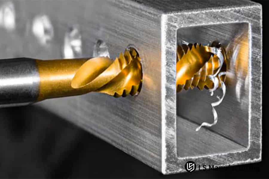
Figure 4: A detailed view of a gold spiral tap forming interior threads by LS Manufacturing
LS Manufacturing: Engine Cylinder Head Threaded Hole Machining Optimization Project
Mass production of autos requires that the threading process be stable to ensure that cost and quality can be competed for. Below is a thread taps guide and the LS Manufacturing solution to a problem in the production of an engine cylinder head in the following manner:
Client Challenge
The problem with the clientrevolved around a grinding machining constraint while drilling M10x1.25 threading holes on gray cast iron (Grade G3500) engine cylinder heads. The taps would change every 800 holes, which is resulting in some irregularity of threads, constant changes, as well as overall scraping of 3% percent. The prime reason is that the taps are of conventional material of high-speed steel.
LS Manufacturing Solution
Our technical solution was capable of addressing the root causes, which were related to the worn-out and chipped evacuation. In our proposal, the maximum anti-wear resistance was provided by a powder metallurgy HSS tap with TiN coatings. Cutting parameters were also optimized properly for 12 m/min, which had a value of 1.19 mm/rev for the feed rate value. Additionally, a through tool coolant with a pressure of 1.2 MPa was used, which had the aim of cooling the cutting edge and evacuating chips, given that the resulting process was capable of performing uninterrupted machining cycles.
Results and Value
This ensured that the average life of the hole increased by 3,500, which is an increase by 337%. There was a reduction by 75% in tool changes, while the quality of the threads was improved to 6H, thereby eliminating the 3% scrap rate altogether. This is additionally coupled with an annual savings of ¥120,000 from the tool costs, apart from ensuring that the level of satisfaction with the result is 100%.
Therefore, this particular case offers our viewpoint on how tooling can be viewed, not only from a commodity point of view, but more specifically from a total engineered systems point of view, and how that particular approach can assist in solving challenging manufacturing issues, such as how LS Manufacturing utilizes their level of technical expertise and focus on partnerships to effectively tap threads for their customers.
Looking to improve thread tapping performance and cost-effectiveness? Explore the ultimate guide to precision machining taps and optimize your CNC milling.

Analysis Of Future Trends And Innovation In Thread Machining Technology
The future of thread production technology would be to push forth the boundaries of traditional variables and maintenance as adaptive, predictive, and highly efficient technology. In a nutshell, it can be said that the biggest challenge for this technology would be to ensure that there is no unpredicted downtime and/or variation in quality as it makes the threading technology intelligent and self-optimizing in the following areas of innovation:
Implementing Predictive Analytics for Proactive Tool Management
Uncertain breakage in taps affects the continuity of production in the production line. Sensors for the measurement of torques and vibrations in the production line in real time while implementing the process of CNC thread tapping are being employed by us. Accordingly, the tool life prediction using a high degree of accuracy of over 90% has been put in the model by the algorithm trained by patterns of breakage.
Developing Advanced Coatings for Extreme Application Longevity
Standard coatings fail prematurely in challenging materials like high-temperature alloys. Our innovation involves nanoscale multilayer coatings, such as TiAlN with integrated solid lubricants like MoS2. This architecture provides a hard, thermally stable outer layer while the lubricant reduces friction at the chip-tool interface. The result is a demonstrable 30%+ increase in tool life in abrasive and adhesive materials, directly enhancing thread tap performance.
Deploying Micro-Lubrication for Precision and Sustainability
It is less effective for flood lubrication to carry out deep hole threading and results in material wastage. This drawback can be overcome with the help of minimum quantity lubrication by aerosolizing. The small volume of the MQL lubricant (50-100 ml/h) may be precisely atomized here so that the cutting edge gets sufficient lubrication. This drastically reduces thermal shock and friction, enabling higher speeds and feeds while improving chip evacuation and surface finish, which is critical for advanced precision machining services.
Creating Adaptive Control Systems for Process Stability
Inconsistencies in the level of hardness of the material indicate corresponding inconsistencies in the level of thread quality. But as one foresees the future, there comes the concept of adaptive control systems of the feed rate. These apply the principle of measurement of the spindle load in real-time to the extent that the control of the rate of the feed is made dependent on the possibility of the existence of hard spots and voids in the material.
This analysis outlines a tangible roadmap from reactive to predictive and adaptive threading. It details how integrating data analytics, material science, and closed-loop control directly solves the pressing challenges of downtime, tool cost, and quality assurance. This forward-looking, solution-oriented approach defines the next generation of high-reliability CNC thread tapping and precision machining services.
FAQs
1. How to choose the suitable tap type for various materials?
Depending upon hardness and strength, the material could be of any type. Application of cobalt high speed steel taps for cutting stainless steel materials, application of spiral point taps for aluminum alloys cutting, and oxide-treated taps for cutting different types of cast irons.
2. How will you know when a tap needs a change?
That is to say, if the torque was increased by 15%, the surface roughness of the thread area became deteriorated, or if the dimensions were out of tolerance, then a new tap had to be substituted immediately, as it was going to produce defective products on a large scale.
3. Should rigid tapping or flexible tapping be used for CNC tapping?
For accurate threads, rigid tapping is recommended, while flexible tapping is best done in deep holes or in difficult materials. This depends on the precision of the machinery.
4. How to effectively extend the service life of taps?
Optimizing cutting factors, using the right coating on the tap, and cooling and lubrication. Regular checkups on the tap for wear are required
5. How to set the cutting speed when machining different materials?
Steel: 20-30 m/min, stainless steel: 10-20 m/min, aluminum alloy: 30-50 m/min. Specific speeds should be determined through trial cuts.
6. What are the common causes of tap breakage and how to prevent them?
These include poor concentricity, poor evacuation of chips, and improper process parameters. The corrective measures include making corrections on the fixture, optimizing the process, and observing the process.
7. How to evaluate whether the thread machining quality is qualified?
Use the thread gauges to check, measure the surface finish by the roughness tester, and do the 100% inspection of the critical dimensions.
8. How much impact does tap coating have on machining performance?
An appropriate layer may prolong the lifespan by 2-3 times. TiN is all-round, TiCN has wear resistance, whereas AlCrN has high-temperature resistance. To order high-precision parts utilizing advanced tool coatings, get an accurate quote from LS Manufacturing today.
Summary
With the help of science used in selecting taps as well as optimizing the process, it will be possible to enhance efficiency and quality while machining thread, as well as optimize production cost.
For services in machining threads in the industry or even a complimentary analysis with regards to the products mentioned, please coordinate with the technical experts of LS Manufacturing. In relation to that, we would like to determine the capability of your current thread tap with a complimentary report on how improvements can be achieved in relation to efficiency, quality, and cost.
Ready to optimize your thread tapping? Explore the Ultimate Guide to Precision Machining Services for peak performance and cost savings.
📞Tel: +86 185 6675 9667
📧Email: info@lsrpf.com
🌐Website: https://lsrpf.com/
Disclaimer
The contents of this page are for informational purposes only. LS Manufacturing services There are no representations or warranties, express or implied, as to the accuracy, completeness or validity of the information. It should not be inferred that a third-party supplier or manufacturer will provide performance parameters, geometric tolerances, specific design characteristics, material quality and type or workmanship through the LS Manufacturing network. It's the buyer's responsibility. Require parts quotation Identify specific requirements for these sections.Please contact us for more information.
LS Manufacturing Team
LS Manufacturing is an industry-leading company. Focus on custom manufacturing solutions. We have over 20 years of experience with over 5,000 customers, and we focus on high precision CNC machining, Sheet metal manufacturing, 3D printing, Injection molding. Metal stamping,and other one-stop manufacturing services.
Our factory is equipped with over 100 state-of-the-art 5-axis machining centers, ISO 9001:2015 certified. We provide fast, efficient and high-quality manufacturing solutions to customers in more than 150 countries around the world. Whether it is small volume production or large-scale customization, we can meet your needs with the fastest delivery within 24 hours. choose LS Manufacturing. This means selection efficiency, quality and professionalism.
To learn more, visit our website:www.lsrpf.com.