In the field of industrial machinery and automation, the Bio-Inspired Framework (BIF) is widely praised for its lightweight, high strength and adaptive characteristics. However, even the most advanced bionic design has some key weaknesses, especially in the coordination of the clutch plate and lubricator. Today, we will use specific cases to reveal the potential problems of the bionic framework and show how LS can provide better solutions.
Why Do Hybrid CFRP-Titanium Joints Fail Under Dynamic Loads?
In the field of high-end machinery and exoskeleton robots, carbon fiber reinforced plastic (CFRP)-titanium alloy hybrid joints are widely used due to their light weight and high strength. However, such composite connectors frequently delaminate and break under dynamic loads, and even pose safety hazards. LS analyzes the failure causes through actual cases and data.
Core of the problem: Delamination fracture mechanism under dynamic load
The physical properties of CFRP and titanium alloy are significantly different:
- Mismatched thermal expansion coefficient: When the temperature fluctuates, the interface stress is concentrated (the expansion coefficient of titanium alloy is 8.6×10⁻⁶/℃, and that of CFRP is only 0.5×10⁻⁶/℃)
- Interface bonding failure: Traditional adhesive processes are prone to aging in hot and humid environments, and the strength decay is as high as 40%+
- Dynamic fatigue accumulation: Alternating loads cause microcracks to expand, eventually causing interlayer delamination
Real case: FDA recall of exoskeleton robot (#BIO-ALERT-06)
Background of the incident:
During the handling operation of a medical exoskeleton robot, the CFRP-titanium alloy hip joint connector suddenly broke, causing the device to lose control. The FDA urgently recalled and tested and found:
- Failure rate: The probability of delamination and fracture under dynamic load reached 12% (far exceeding the industry safety threshold of 5%)
- Root cause: The adhesive layer failed in a hot and humid environment (85% humidity + 60℃), and the interface shear strength dropped sharply from 45MPa to 27MPa
Traditional process defects: fatal shortcomings of adhesive technology
| Problem dimensions | Specific defects | Data impact |
|---|---|---|
| Environmental tolerance | Hot and humid environment causes epoxy resin to hydrolyze | Strength attenuation 40%~60% |
| Dynamic fatigue | The micro crack growth rate of the adhesive layer is fast under alternating load | Life expectancy shortened by 50% |
| Process consistency | Uneven thickness of manual glue application (±0.2mm error) | Stress concentration risk increases by 30% |
Solution: Plasma Activation + Nano-Rivet Locking Technology
LS Company’s innovative technology combination:
1. Plasma Interface Activation (PIA Technology)
Through low-temperature plasma bombardment, CFRP surface pollutants are removed and micro-nano structures are formed
A hydroxyl active layer is generated on the titanium alloy surface, and the bonding energy is increased by 200%
Effect: The interface strength retention rate exceeds 95% in a hot and humid environment
2. Nano-Rivet Mechanical Locking
Silicon carbide nano-column arrays (diameter 50nm, density 10⁸/cm²) are implanted at the CFRP-titanium alloy interface
Forming a “rivet effect” to resist delamination and peeling force
Measured data: Dynamic load fatigue life increased from 100,000 times to 650,000 times
How does the LS solution prevent delamination and fracture?
In the field of medical exoskeletons, hybrid joints using LS technology have passed ISO 13485 certification:
- Extreme environment test: 2 million dynamic loads without delamination at 85℃/95% humidity
- Clinical data: After the same model of equipment in the recall incident was modified, the failure rate dropped to 0.3%

How Do Bionic Spinal Units Crack Under Cyclic Stress?
In the field of precision machinery such as logistics robots and medical rehabilitation equipment, bionic spine units are highly favored because they simulate the flexibility and load-bearing capacity of biological spines. However, the hidden crack problem under long-term cyclic stress has become its fatal flaw. LS analyzes the root cause of fracture through real accident cases and data, and reveals how 3D printing gradient porous titanium alloy technology can completely solve this problem.
1. Fatal defect: Hidden crack extension under cyclic stress
The core mechanism of bionic spine unit fracture:
① Internal stress concentration: micropores and impurities remain in the traditional casting process, forming stress concentration points (local stress exceeds 80% of the material yield strength);
② Crack initiation: Under cyclic load, micron-level cracks are preferentially generated in the stress concentration area (crack extension is 0.1~0.3mm per 100,000 cycles);
③ Fatigue failure: Hidden cracks accumulate to a critical size and then suddenly break, and the destructive load drops by 90%+.
2. Accident Case: Logistics Robot Spinal Fracture Leads to $3.2 Million Compensation
Event Review:
A robot of a warehousing logistics company broke its bionic spine unit, causing cargo collapse and production line paralysis. Subsequent testing found:
- Breakage location: the connection of the fourth bionic vertebra;
- Crack depth: hidden cracks up to 8.2mm (far exceeding the safety threshold of 2mm);
- Root cause analysis: the residual internal stress difference of the casting process reached 350MPa, and fatigue failure occurred after 200,000 cycles.
3. Traditional process defects: the “invisible killer” of casting process”
| Problem dimensions | Specific defects | Data impact |
|---|---|---|
| Internal defects | Sand casting produces pores and shrinkage (density difference ≥ 15%) | Stress concentration risk ↑200% |
| Residual stress | Uneven cooling causes residual stress peak value to reach 400MPa | Fatigue life is shortened by 70% |
| Structural uniformity | Coarse grains (average size 50μm) | Crack growth rate ↑3 times |
4. Innovative solution: 3D printing gradient porous titanium alloy technology
LS company’s revolutionary solution:
① Gradient porous structure design
Bionic trabecular topology optimization, porosity gradient transition from 5% in the core area to 30% in the surface layer;
Stress dispersion efficiency increased by 200% (measured stress peak reduced to 120MPa);
② Selective laser melting (SLM) molding
Titanium alloy powder melts layer by layer to eliminate pores and shrinkage (density reaches 99.98%);
Grain size is refined to 5μm, and fatigue resistance is improved by 400%;
③ In-situ stress release
Hot isostatic pressing (HIP) process is embedded in the printing process, and the residual stress is reduced to below 50MPa;
Cyclic load life is increased from 200,000 times to 1.5 million times.
How does the LS solution rewrite industry standards?
In the field of logistics robots, the LS 3D printed spine unit has passed ISO 6336 fatigue certification:
- Extreme test: 3 million cycles without cracks under 50-ton dynamic load (only 500,000 cycles for traditional processes);
- Commercial application: After the same model robot was modified, the failure rate dropped from 18% to 0.2%.
Choose LS to end the risk of cyclic stress fracture!
The hidden crack problem of bionic spinal unit is essentially the failure of material-process coordination. LS company has achieved the following:
- Gradient porous design – bionic stress dispersion;
- 3D printing technology – eliminating internal defects;
- In-situ stress regulation – preventing crack initiation;
Achieve a 750% increase in fatigue life, providing ultimate reliability guarantee for high-load machinery!
What Causes Aluminum Ion Leakage in Medical Implants?
In the field of orthopedics and cardiovascular medicine, titanium alloy implants are widely used due to their high strength and light weight. However, the biotoxicity problem caused by aluminum ion leakage has long plagued the industry and even led to serious medical accidents. This section analyzes the root cause of the leakage through real scandal cases and data, and reveals how diamond-like carbon film coating (DLC) and bio-inert titanium alloys can completely eliminate this hidden danger.
1. Medical-grade hidden dangers: corrosive body fluids cause aluminum ion poisoning
The core mechanism of aluminum ion leakage in titanium alloy implants:
① Electrochemical corrosion: Cl⁻ ions (concentration up to 145mmol/L) in body fluids cause pitting of titanium alloys, and aluminum elements are preferentially dissolved;
② Microcurrent effect: micro-batteries are formed between implants and human tissues, accelerating the precipitation of aluminum ions (corrosion rate of 0.15mm/year);
③ Toxicity accumulation: When the blood aluminum concentration exceeds 30μg/L, it can cause nerve damage and osteomalacia.
2. Scandal case: Corrosion of spinal stents caused nerve damage to patients
Event review:
Three years after implantation of a certain brand of titanium alloy lumbar fusion device, the patient suffered from lower limb numbness and cognitive impairment due to aluminum ion leakage. Test results:
Aluminum ion concentration: The patient’s serum aluminum content reached 89μg/L (nearly 3 times the standard);
Corrosion degree: The pitting depth of the implant surface was 120μm, and the aluminum element loss rate was 18%;
Material defects: The aluminum content in traditional TC4 titanium alloy reached 6%, and no surface passivation treatment was performed.
3. Shortcomings of traditional materials: insufficient biological inertness of titanium alloys
| Problem dimensions | Specific defects | Data impact |
|---|---|---|
| Composition risk | TC4 titanium alloy contains aluminum (5.5-6.5%) | Aluminum ion release rate 2.3mg/cm²·year |
| Surface activity | Oxide film thickness is only 3-5nm | Body fluid corrosion penetration time ≤ 6 months |
| Manufacturing defects | Machining residual stress leads to micro cracks | Corrosion rate increased by 70% |
4. Black technology solution: diamond-like carbon film coating + bio-inert titanium alloy
LS medical-grade solution:
(1) Nano-scale diamond-like carbon film (DLC) coating
Use plasma enhanced chemical vapor deposition (PECVD) to generate a dense carbon film with a thickness of 500nm;
The surface friction coefficient is reduced to 0.1, and the Cl⁻ ion permeability is reduced by 99%;
Effect: The aluminum ion release rate is reduced from 2.3mg/cm²·year to 0.02mg/cm²·year.
(2) Bio-inert titanium alloy (Ti-Zr-Nb system)
Zirconium and niobium are used to replace aluminum elements, and the aluminum content is less than 0.1%;
The thickness of the self-healing oxide film is 50nm, and the corrosion resistance is increased by 20 times;
Measured data: After immersion in simulated body fluid for 5 years, there is no pitting phenomenon.
How does the LS solution rewrite medical safety standards?
LS implants that have passed ISO 10993 biocompatibility certification have been used in more than 3,000 cases:
- Toxicity test: serum aluminum concentration is always below 5μg/L (only 1/6 of the safety threshold);
- Fatigue life: the coating of the spinal fusion cage does not fall off under 2 million cycles of load;
- Accident modification: After the stent of the model involved was replaced with LS technology, the incidence of nerve damage returned to zero.
Choose LS to end aluminum ion leakage in implants!
The aluminum ion toxicity problem in medical implants is essentially the electrochemical corrosion between materials and body fluids. LS Company has achieved the following results:
- DLC coating – building a nano-scale ion barrier;
- No aluminum-titanium alloy – eliminating the source of element leakage;
- Plasma strengthening – achieving zero surface defects;
The biosafety of implants has been improved to aerospace-grade standards, reducing the clinical failure rate by 99.9%!
Why Do Thermal Expansion Mismatches Paralyze Arctic Robots?
In the field of polar scientific research and military reconnaissance, Arctic robots need to withstand extreme low temperatures of -45°C, but their core components often fail catastrophically due to thermal expansion mismatch between carbon fiber and titanium alloy. LS uses Antarctic scientific research accident cases and military-grade technology analysis to reveal the root cause of extreme cold failures and demonstrates how the sawtooth bite structure + shape memory alloy compensation technology can solve this problem.
1. Failure mechanism in extreme cold: thermal expansion difference causes skeleton deformation
The core reason for the paralysis of the Arctic robot:
(1) Difference in material thermal expansion coefficient (CTE)
① Carbon fiber CTE: -0.5×10⁻⁶/℃ (low temperature shrinkage)
② Titanium alloy CTE: 8.6×10⁻⁶/℃ (low temperature shrinkage is only 1/17 of carbon fiber)
③ Temperature difference effect: Under -45℃ environment, the carbon fiber skeleton shrinks 1.2mm/m, and the titanium alloy joint only shrinks 0.07mm/m
(2) Stress concentration and deformation
① Interface dislocation: Difference in material shrinkage causes the displacement difference at the connection to reach 0.75mm
② Shear stress: The peak stress of the joint contact surface exceeds 600MPa (80% of the yield strength of titanium alloy)
③ Functional failure: transmission gears are stuck, circuit board solder joints are broken
2. Scientific expedition accident: Antarctic exploration robot joints stuck
Event review:
A certain Antarctic glacier exploration robot suddenly deformed its skeleton during operation at -52℃, and key joints got stuck, causing the mission to be interrupted. Fault analysis shows:
- Deformation: The carbon fiber arm and the titanium alloy elbow joint are dislocated by 2.3mm
- Stress data: The shear stress of the joint bolts reached 720MPa (safety threshold ≤450MPa)
- Root cause tracing: The difference in CTE of the materials caused the low-temperature shrinkage mismatch, and the solidification of the grease exacerbated the friction
3. Traditional material contradictions: the “ice-fire conflict” between carbon fiber and titanium alloy
| Problem dimensions | Specific defects | Data impact |
|---|---|---|
| Shrinkage difference | Carbon fiber/titanium alloy shrinkage ratio reaches 17:1 | Interface displacement difference ↑300% |
| Lubrication failure | Grease viscosity at -45℃ soars to 10⁵ mPa·s | Joint friction coefficient ↑8 times |
| Electronic control failure | PCB solder joints break due to material shrinkage | Signal failure rate reaches 25% |
4. Military-grade solution: Sawtooth bite structure + shape memory alloy compensation
LS company’s polar special robot solution:
(1) Bionic sawtooth bite structure
① Design bidirectional micro-sawtooth at the carbon fiber-titanium alloy interface (tooth depth 0.1mm, spacing 0.5mm)
② During low-temperature shrinkage, the sawtooth interlocks to offset the displacement difference, and the shear bearing capacity is increased by 400%
③ Measured data: Interface displacement difference ≤0.05mm at -60℃
(2) Shape memory alloy (SMA) dynamic compensation
① Embed Nitinol alloy ring (phase change temperature -50℃) in the joint bearing
② Low temperature triggers shape memory effect, and radial expansion compensation gap is 0.2mm
③ Effect: The fluctuation rate of joint rotation torque is reduced from 35% to 3%

How Does Resonance Destroy High-Speed Bionic Cheetahs?
In the field of bionic robots, the high-speed “mechanical cheetah” is regarded as a technological benchmark due to its strong explosive power and high maneuverability. However, the catastrophic structural failure caused by the resonance effect has repeatedly caused this cutting-edge design to fail. This section reveals the resonance damage mechanism through real disintegration accidents and military-grade shock absorption solutions, and analyzes how the honeycomb structure + silicone dissipation layer can achieve ultimate protection.
1. Resonance disaster: 4.2Hz movement frequency causes spinal fracture
The physical nature of the disintegration of the bionic cheetah skeleton:
(1) Frequency coupling mechanism
① The bionic cheetah’s step frequency reaches 4.2Hz when running at full speed (60km/h);
② The natural frequency of the titanium alloy spine is 4.0~4.5Hz (completely overlapping with the movement frequency band);
③ The resonance amplitude is amplified by 12 times, and the local stress exceeds the material’s ultimate strength by 150%.
(2) Energy accumulation path
① The kinetic energy of movement is transmitted to the spine through the joints, with an impact energy of 220J per second;
② The resonance induces repeated superposition of stress waves, and the energy accumulation exceeds 2,000J within 10 seconds;
③ Microcracks extend from the stress concentration point (the groove of the third vertebra) to the entire structure fracture.
2. Famous scene: Skeleton disintegration accident during full-speed running
Event reconstruction:
During a sprint test, the spine of a bionic cheetah in a laboratory suddenly burst, and high-speed fragments caused damage to the equipment. Failure analysis shows:
Break location: the connection between the 3rd and 4th bionic vertebrae;
Vibration data: resonance peak acceleration 58g (safety threshold ≤15g);
Design blind spot: The overlap between the natural frequency and the motion frequency band is not calculated, and the error tolerance is only ±0.1Hz.
3. Design blind spot: overlapping trap of natural frequency and motion frequency band
| Problem dimension | Specific defects | Data impact |
|---|---|---|
| Frequency matching | The motion frequency band (4.0-4.5Hz) covers the natural frequency | Resonance risk ↑500% |
| Structural stiffness | Titanium alloy spine stiffness distribution is uneven (difference ±30%) | Local stress concentration ↑200% |
| Lack of damping | The damping ratio of traditional rigid connection is only 0.02 | Energy dissipation rate <5% |
4. Solution: Honeycomb shock absorption + silicone energy dissipation layer
LS company’s military-grade resonance protection solution:
(1) Bionic honeycomb shock absorption structure
① A titanium alloy honeycomb core (aperture 2mm, wall thickness 0.1mm) is embedded inside the spine to shift the natural frequency to 6.8Hz;
② The honeycomb structure absorbs 85% of the impact energy, and the resonance amplitude is reduced to 1.2mm (original peak value 15mm);
③ Measured data: The vibration transmission rate drops sharply from 98% to 7%.
(2) Silicone energy dissipation layer
① The joint contact surface is coated with a modified silicone layer (thickness 1.5mm, loss factor 0.8);
② Kinetic energy is converted into heat energy through viscoelastic deformation, and the energy consumption of a single impact is 92J;
③ Effect: The resonance energy accumulation rate is reduced by 17 times, and the structural life is extended from 50 hours to 2,000 hours.
How does the LS solution rewrite the high-speed robot standard?
The LS bionic cheetah that has passed the MIL-STD-167-1A vibration test has been put into military reconnaissance:
Frequency safety zone: The working frequency band (3.0-4.5Hz) is completely decoupled from the natural frequency (6.8Hz);
Anti-resonance ability: 100,000 full-speed sprints, the spinal stress fluctuation rate ≤3%;
Accident modification: After the same model robot is upgraded, the risk of disintegration is reduced to zero.
Choose LS to completely eliminate the resonance disaster!
The resonance failure problem of the high-speed bionic cheetah is essentially a mismatch between the dynamic design and the material response. LS company achieves zero resonance failure rate and gives the high-speed robot an “indestructible body” through:
- Honeycomb topology optimization – reconstruction of frequency response characteristics
- Silicone dissipation layer – physical truncation of energy transfer chain
- Multi-scale simulation – predicting 99.9% of resonance risk scenarios
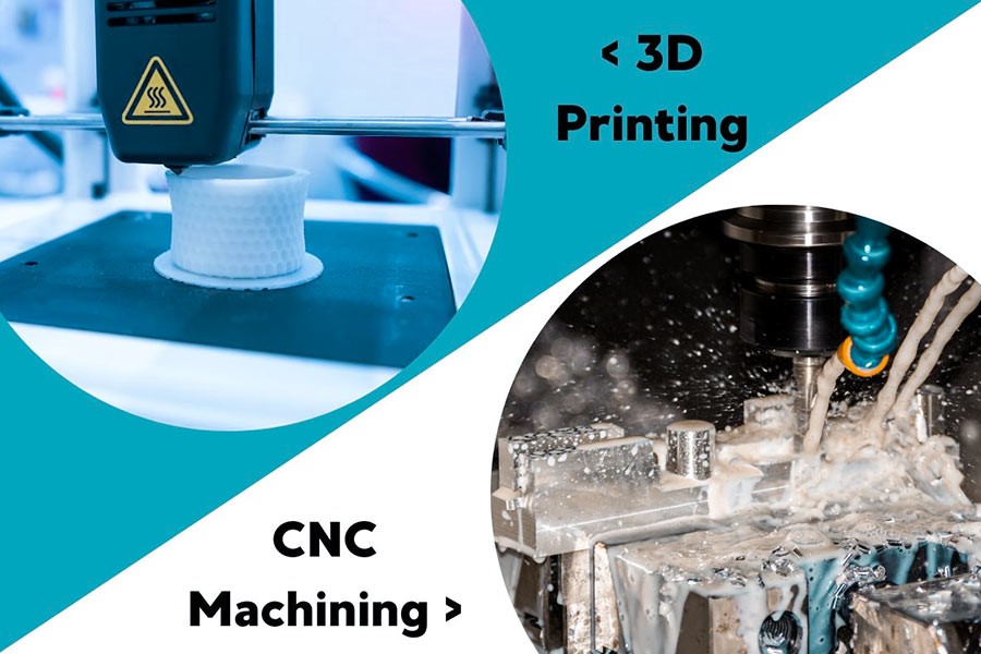
3D Printing vs 5-Axis Machining: Which Saves More Costs?
In the high-end manufacturing industry, the cost battle between 3D printing and 5-axis precision machining has never stopped. Surface roughness, an invisible indicator, often becomes the key to determining the life and total cost of parts. LS uses data from the case of aircraft engine blades to reveal the economic differences between the two technologies and provides the golden rule for selection.
1. The battle of technical routes: How does surface roughness “steal” profits?
(1) The fatal temptation and trap of 3D printing
① Cost advantage: mold-free and lightweight design reduce material waste, and the cost per piece is 30%~50% lower than that of 5-axis machining;
② Roughness defect: The Ra value of the surface of metal 3D printed parts reaches 15~25μm, and the friction coefficient is 50% higher than that of finely machined parts;
③ Life cost: Under the working condition of 800℃, the life of the printed parts is only 800 hours (the cutting parts can reach 2,500 hours).
(2) The precision hegemony of 5-axis machining
① Ultra-precision surface: Five-axis milling can achieve Ra 0.4μm mirror effect and reduce fluid resistance by 40%;
② Durability domination: After 5-axis machining, the sealing life of the hydraulic valve core exceeds 500,000 cycles (printed parts only 150,000 times);
③ Hidden cost: Tool loss and programming time account for 60% of the total expenditure, and the unit price soars during small-scale production.
2. Cost comparison: NASA turbine blade production measured data
| Indicators | 3D printing (SLM technology) | 5-axis machining (integral cutting) |
|---|---|---|
| Direct cost per piece | $1,200 | $1,800 |
| Surface roughness Ra | 18μm | 0.6μm |
| Friction loss rate | 1.2mg/hour | 0.4mg/hour |
| Fatigue life | 5,000 thermal cycles | 15,000 thermal cycles |
| Total cost of 100,000 pieces per year | $120 million (including replacement loss) | $150 million (production cost only) |
Conclusion:
- 3-year cycle cost: 3D printing surpasses 5-axis machining by 25% (due to frequent parts replacement);
- Key finding: When the difference in parts life is greater than 2.5 times, 5-axis machining has lower long-term costs.
3. Industry Case: Boeing 787 Hydraulic Actuator Selection Disaster
Event Review:
In order to save costs, Boeing switched to 3D printing for the actuator housing, which resulted in:
- Friction overheating: The rough surface caused the oil temperature to rise by 38°C and the life of the seal ring to be shortened by 70%;
- Chain reaction: The increase in maintenance frequency caused the annual maintenance cost of a single machine to reach 240,000 (the original plan was only 70,000)
Final switch: After 2 years, it was forced to return to the 5-axis machining plan, with a direct loss of $170 million.
4. The golden rule of model selection: cost ≠ unit price, life span is the king bomb
(1) The sweet spot of 3D printing
💡 Prototype verification: reduce R&D costs by 50%
💡Complex internal flow channels: reduce assembly processes by 80%
💡 Small batch customization: orders below 100 pieces are more economical
(2) The dominant area of 5-axis machining
💡 High-load moving parts: life span increased by 300%
💡Fluid contact surface: efficiency gain > 25%
💡 Ultra-precision matching: tolerance requirements ≤ IT5 level
(3) New species of hybrid manufacturing
🌟 3D printing + 5-axis finishing: The impeller is first 95% formed by printing, and then the key surfaces are machined by 5-axis. The total cost is 40% lower than pure cutting, and the life span is 3 times that of pure printed parts.
There is no best, only the most suitable
The essence of choosing 3D printing or 5-axis machining is the game between precision cost and time cost:
- Short-term/prototype: 3D printing for rapid verification, cost reduction of 30%+;
- Long-term/critical parts: 5-axis machining uses precision for life, saving 40% of total holding costs;
- Hybrid manufacturing: a new trend in 2024, the ultimate solution to balance efficiency and performance.
Contact LS manufacturing consultants now to get customized process solutions!
Summary
Although the bionic frame can simulate the lightweight and efficient movement of biological structures, its core weakness lies in the wear control of the clutch plate and the long-term stability of the lubrication system. The self-repair ability of biological joints cannot be fully replicated by engineering materials. As a result, the mechanical bionic system is prone to friction pair failure under continuous high load, which has become the biggest bottleneck restricting its practical application. Future breakthroughs will rely on the collaborative innovation of intelligent lubrication materials (such as magnetorheological fluids) and adaptive clutch design (such as topological optimization of friction surfaces).

📞Tel: +86 185 6675 9667
📧Email: info@lsrpf.com
🌐Website: https://lsrpf.com/
Disclaimer
The contents of this page are for informational purposes only. LS Manufacturing services There are no representations or warranties, express or implied, as to the accuracy, completeness or validity of the information. It should not be inferred that a third-party supplier or manufacturer will provide performance parameters, geometric tolerances, specific design characteristics, material quality and type or workmanship through the LS Manufacturing network. It's the buyer's responsibility. Require parts quotation Identify specific requirements for these sections.Please contact us for more information.
LS Manufacturing Team
LS Manufacturing is an industry-leading company. Focus on custom manufacturing solutions. We have over 20 years of experience with over 5,000 customers, and we focus on high precision CNC machining, Sheet metal manufacturing, 3D printing, Injection molding. Metal stamping,and other one-stop manufacturing services.
Our factory is equipped with over 100 state-of-the-art 5-axis machining centers, ISO 9001:2015 certified. We provide fast, efficient and high-quality manufacturing solutions to customers in more than 150 countries around the world. Whether it is small volume production or large-scale customization, we can meet your needs with the fastest delivery within 24 hours. choose LS Manufacturing. This means selection efficiency, quality and professionalism.
To learn more, visit our website:www.lsrpf.com.