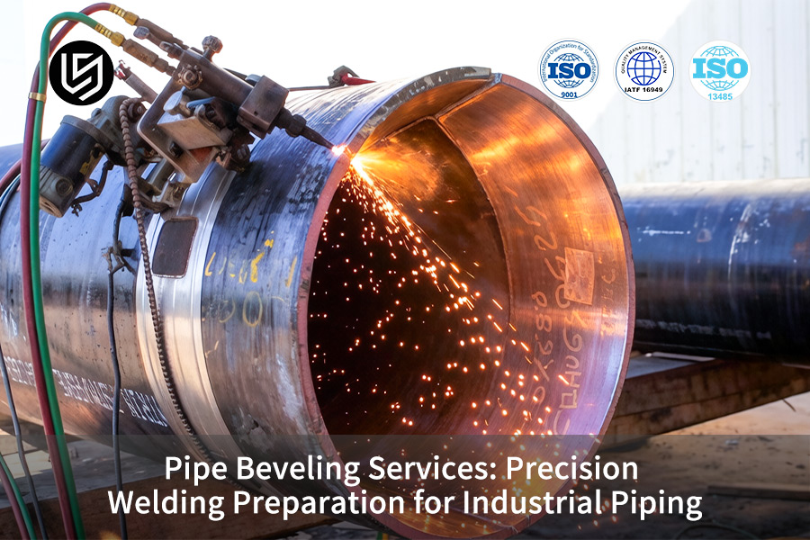
Pipe beveling services are typically mentioned in articles talking about what is pipe beveling; however, when we talk about industrial piping systems for oil and gas or chemical production processes, bevel accuracy becomes crucial for high-pressure welding quality. The problem is that professional beveling is necessary because unprofessional beveling may cause variations in root face or bevel angle, which results in a lack of fusion defect in automatic welding operations that can make rework cost three to five times higher than the cost of initial welding operations.
In the case of LS Manufacturing, pipe beveling services are used in pre-welding preparations, providing 0mm heat affected zone and making sure that all joints meet requirements of precision welding preparation. The following bevel angle stability parameters will help you choose the optimal technological way for complex piping prefabrication.
Pipe Beveling Services: Welding Prep Quick-Reference
| Critical Requirement | Precision Beveling Implementation |
| Bevel Angle & Land Consistency | We produce consistent bevel angle (for example, 37.5°) and land uniformity for consistent weld penetration and root gaps. |
| Face Squareness & Alignment | We guarantee squareness and alignment of the bevel face along the axis of the pipe to avoid welding problems. |
| Burr & Sharp Edge Removal | We use secondary chamfer and deburring process to remove sharp edges from the beveled surfaces to avoid weld defects. |
| Material Hardness Consideration | We vary our tooling and speed depending on whether the pipe is made up of carbon, stainless, or alloy steel. |
| Our Portable & Stationary Solutions | We utilize portable beveling metal welding machines on site for field operations and stationary lathe-style equipment for shop fabrication. |
| Result: Optimal Weld Joint Integrity | Produces a properly prepped surface to ensure total penetration, solid fusion, and a good weld with few flaws. |
| Result: Reduced Welding Time & Cost | Guarantees that welders and fitters are able to work quickly, lowering labor costs and material consumption per weld. |
We address the essential task of pipe end preparation to ensure code-compliant welds of superior quality. Through accurate beveling, we achieve uniform angles, square faces, and sharp edges, which create strong and dependable joints, minimize the time and expense of welding, and enhance the reliability of your industrial piping metal welding system. We offer our professional skills and knowledge to guarantee that each weld joint is prepared for its optimal operation.
Why Trust This Guide? Practical Experience From LS Manufacturing Experts
There are numerous websites on the internet covering the topic of pipe beveling; however, what makes this guide unique? We are practical people, not only theoreticians. In the real life of industrial production, when you have to deal with the harsh realities of battle, you can rely only on accuracy. Our technology is based on the fundamental requirements defined by ASTM International.
Our solutions benefit industries where mistakes are not an option. With subsea pipelines, even a slight defect in the bevel will cause catastrophic damage at high pressures. In chemical plants, errors with the angle on corrosion-resistant alloy pipes will cause early weld failures. We follow National Association for Surface Finishing (NASF) recommendations for our final edge preparation to guarantee smoothness and strength in the weld pools for power plants and shipbuilding.
Everything we teach has come out of trial and error. We know how to achieve the ideal bevel to allow a clean land on duplex stainless steel, the best approach to automate bevelers in pipes at various angles, and how to maintain the same standards through a hundred thousand cuts. It took us sweat, cutting fluid, and x-rays to get it right—we'll show you how.
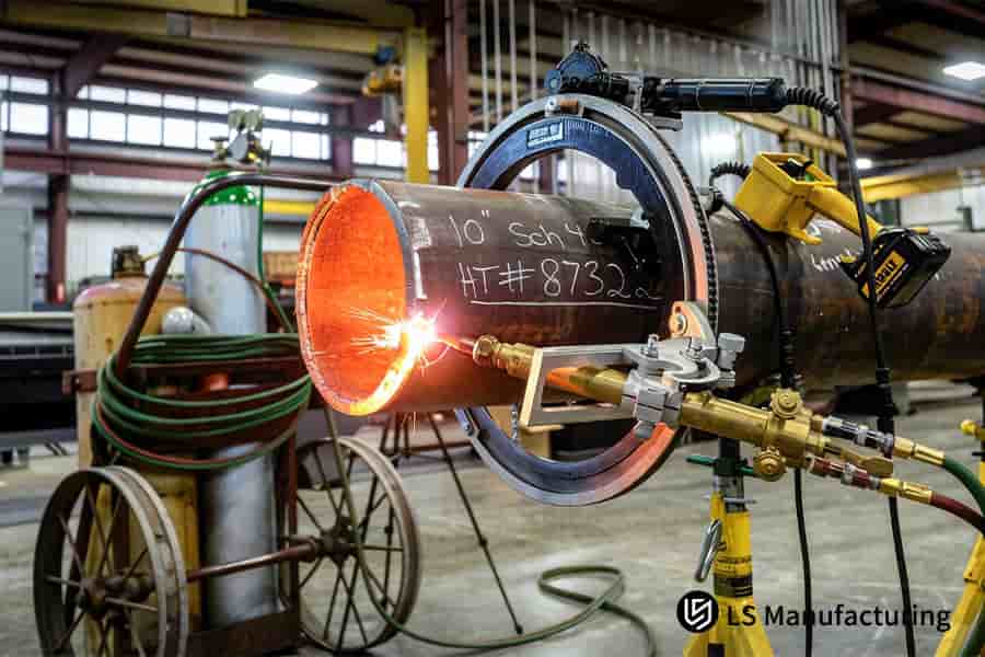
Figure 1: A worker uses a handheld tool to bevel a steel pipe end for subsequent welding in industrial fabrication.
Why Is LS Manufacturing The Premier Choice For Professional Pipe Beveling Services In 2026?
For 2026, maximizing efficiency in field welding will come down to removing any fit-up times associated with preparing the welding surface. The key will be converting the very high ASME standard sinto reality, which requires us to be able to hold our bevel tolerance within ±0.5° in heavy wall piping. Our process allows this precise level of control, thereby facilitating the 30%+ increases in efficiency proven through our system:
Measurement-First Validation Protocol
The process starts with scanning the end of the pipe using a 3D laser system to create a digital benchmark of the end. We then compensate for the natural variations found in the raw material. This allows us to cut based off the real center line of the pipe and lay the groundwork for precision pipe beveling.
Patented Multi-Stage Tooling Process
In the case of thick-walled pipes, single pass cuts cause an imbalance in thermal energy. The remedy is the application of a multi-pass process consisting of roughing, semi-finishing, and finish operations. In this way, we manage the thermal effect and physical strain, thus ensuring that the ±0.5° tolerance is achieved reliably. This consistency is essential for high-integrity metal welding and is one of the main outcomes of our pipe beveling services.
Integrated Human-In-The-Loop Verification
A second validation is necessary for final approval. After machining, the measurements taken using a profile gauge and confirmation using laser scanning are compared against the Welding Procedure Specification of the project by a qualified engineer. The mandatory approval of the engineers at LS Manufacturing ensures that all parts have been manufactured specifically to be used in critical metal welding application.
Technical expertise can be demonstrated through our engineered solutions for converting specifications into tangible results through processes such as compensated machining and thermal control. We address the real issue causing the delays with regard to fit up through these engineered solutions. We will provide you with constructability in demanding metal welding projects.

How Can Metal Welding Services Benefit From High Precision Cold Cutting Beveling Techniques?
The optimal quality of welding is essentially defined during the beveling stage. The heat generated in the thermal cutting process results in a Heat Affected Zone (HAZ) that affects the base metal's structure and properties at the point where the materials connect. Our innovative use of cold cutting technology is the ultimate fix, retaining 100% material integrity to guarantee that welding reaches its maximum potential. Below is a description of our approach:
Eliminating the Heat-Affected Zone (HAZ)
- Our Method: Mechanical Severance. Our approach involves high-force mechanical cutting and machining rather than thermal treatment.
- Technical Rationale: This eliminates metallurgical phase transitions that result from quick heating and cooling.
- Problem Solved: It entirely eliminates the thin 1-2mm brittle surface layer to ensure that the weld joins only with ductile parent metal. This is crucial for high-strength metal welding effectiveness.
Ensuring Dimensional Fidelity for Optimal Weld Geometry
- Our Process: The cold-beveling machine is controlled using computer programming based on 3D measurements.
- Result: It creates a smooth bevel surface with nearly perfect angle and surface finish tolerance.
- Value Delivered: This dimensional accuracy is vital to achieving adequate root gaps and weld penetration, and results in better critical-pressure metal welding performances and forms the basis of our premium pipe beveling services.
Implementing a Verifiable Quality Chain
- Our Protocol: Dual Verification. Each beveled part is subjected to a two-level verification process.
- Step 1 - Non-Destructive Testing (NDT): Dye-penetration test confirms the absence of micro-cracks on the beveled surface.
- Step 2 - Material Certification: Conformity certificate provides the traceability of the procedure to the material lot number, thereby confirming the material integrity used. This quality chain is what makes professional metal welding services.
As evident, achieving excellent metal welding starts way before ignition. Technical proficiency of our services is demonstrated through the adoption of cold cutting technology and the rigorous process that comes with it, which solves the fundamental flaw in the quality of welding joints. We not only offer you a beveled edge but an extension of your parent metal properties, ensuring that your performance-critical metal welding at optimal levels for the duration of its design life.
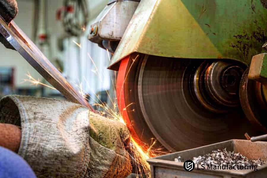
Figure 2: A grinder finishes the bevel edge on a stainless steel pipe for precision fit-up in pipe welding.
Why Should Engineers Prioritize Precision Pipe Beveling For Automated Orbital Welding Systems?
Orbital welding machines require total consistency in terms of joint preparation, especially the root face, to ensure good welding quality. However, the primary problem lies in the geometric variance that necessitates dynamic adjustment in the welding procedure. This paper explains a unique approach, using closed-loop metrology, to attain the required tolerances needed for perfect metal welding operations and 100% non-destructive testing (NDT).
| Objective | Our Engineered Solution | Technical Outcome / Solved Problem |
| Achieve Dimensional Consistency | Use a closed-loop laser metrology technique that can measure the root face while machining. | Allows real-time corrections of the tool paths, enabling accurate control of the root face thickness tolerance to ±0.05mm. This is crucial for achieving high-purity metal welding. |
| Ensure Process Stability | Include the measurement information into the CNC control unit to allow automatic adjustments after each rotation. | Reduces power supply variations, ensuring the same power supply and fusion throughout the process for critical-path metal welding. |
| Validate & Document Quality | After processing, use a laser scan to generate a 3D profile map of each bevel to be documented as quality validation for each part. | Presents quantifiable evidence of quality consistency of parts that allows stringent qualification of the automated welding process. |
The concept of precision pipe beveling involves the process being controlled by digital technology through feedback loops. Eliminating the source of the welding parameters fluctuation—joint geometry—our technology offers components for optimal performance of automated systems. Such technological precision allows obtaining documented quality consistency necessary for the crucial application of metal welding, defining our industry leading standard of industrial pipe beveling technology.
What Makes Welding Preparation Services Critical For Deep Sea And High Pressure Piping?
Deep sea and high pressure pipes require a joint that is absolutely flawless, since conventional preparation techniques create too much stress and increase costs substantially. In this regard, the main problem lies in finding the most optimized configuration of the joint which can withstand high static and dynamic loads and minimize the costs. For this purpose, we use a unique U groove preparation technique as a solution, providing a number of benefits in terms of performance and cost optimization:
Geometry-Specific Process Development
Each project starts with a DFM study which involves analyzing the pipe material, its wall thickness, and operating pressures. The findings of the DFM study determine the best configuration of the U-groove profile, which includes its root face width, groove angle, and radius. The selection is driven by finite element analysis to minimize stress concentration, a critical factor for high-pressure metal welding integrity. This upfront engineering defines the parameters for our custom pipe beveling service.
Precision Machining with Contour Control
CNC machining of the groove design must be done through a contouring process using the appropriate machining capabilities. A specially developed form-ground cutting tool will be used with a radius of the desired value. The machining process will ensure that there is consistent engagement between the tool and the workpiece during the whole operation to deliver the intended groove design. This level of accuracy is required to guarantee uniform penetration in thick-section metal welding for deep sea piping applications.
Validated Outcome for Performance Assurance
Upon completion of the machining process, the geometry gets validated via custom contour gauge, as well as laser scanning, in order to guarantee that critical dimensions, such as radius at the root, are within ±0.1mm tolerance band. Additionally, we do an analysis pertaining to volume of weld calculated, which proves our claim that 25% less weld volume is needed than when using standard V groove welding preparation services provided by competitors.
Our expertise in this field comes about through a number of processes that involve optimization of joint geometry up until quantitative proof thereof. Rather than offer conventional services that only look at problems related to structural integrity and cost effectiveness, we manufacture a product suitable for the extreme environment. Custom pipe beveling process is an integral step that guarantees longevity of your deep sea piping welds.
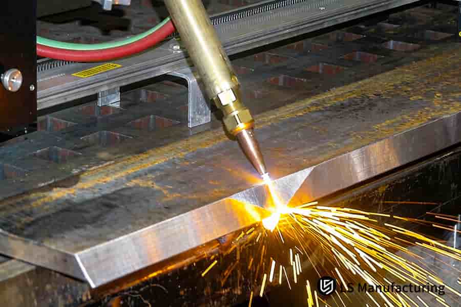
Figure 3: An automated beveling head machines a steel pipe end, the key welding preparation services for structural joints.
How Does Industrial Pipe Beveling Manage Dimensional Stability In Large Diameter Thick Walled Pipes?
For large diameter pipes with heavy walls, gravity and handling always create out-of-round conditions that make it impossible for theoretical centerlines to be accurate. By machining the bevel based on such a flawed datum plane, an off-center joint will result, necessitating difficult on-site adjustments and creating undesirable stresses during assembly. We have devised a technique by which the true mechanical axis of the pipe is dimensional stability, and a concentric bevel is machined on it.
Quantifying Actual Geometry via 3D Scanning
- Process: Our initial step involves the use of superior scanning devices to conduct a laser scan on the outer and inner surface of the pipe ends.
- Outcome: A 3D model of the pipe, which depicts its precise measurement with respect to ovality, is thus created.
- Problem Solved: It replaces assumptions with empirical data, establishing the real-world baseline essential for all subsequent industrial pipe beveling for heavy-duty metal welding.
Implementing a Non-Distorting, Self-Centering Fixture
- Process: The custom-made clamp holder is engineered based on the scan data that was acquired.
- Outcome: It will grip the workpiece properly without trying to deform it into an artificial circular shape; everything with respect to its center.
- Value Delivered: Provides a stable foundation for v while preserving its geometric characteristics, vital for any high-cycle metal welding projects.
Executing Adaptive, Compensated Machining
- Process: The computerized numerically controlled cutting sequence is programmed adaptively using scan data.
- Outcome: The machine will follow the prescribed toolpaths to produce a perfectly concentric bevel face relative to the axis of the pipe.
- Result: This creates an accurate geometrical preparation on an irregular pipe, resulting in ideal alignment for severe-service metal welding of large diameter pipes without fit-up stresses.
This method illustrates that the key to accuracy lies in adjustment and not in presupposition. We resolve the problem of field misalignment by cutting based on the actual datum and not the theoretical one. Our system guarantees that our components will perfectly align at the very first trial, which is the ultimate standard for handling dimensional stability in expensive and intricate piping systems that cannot be forced to align.
Can Custom Pipe Beveling Services Adapt To Exotic Alloys And High Strength Steel?
Successful exotic alloys preparation for high-quality welding calls for proper metallurgical control in order to avoid work hardening and damage to the cut edge. The custom pipe beveling process makes use of physics methods tailored specifically to the alloy, ensuring that its integrity remains intact. Thus, the resultant beveled area is not only ready for the next step, but is ideally suited for high-performance metal welding, creating the perfect platform for the joint.
| Challenge | Our Engineered Solution | Key Result |
| Preventing Work Hardening | Use of our patented database for geometry setting, tool feed and cutting speed, enabling continuous chip formation. | Breaks down the brittle and hardened outer layer, responsible for initiating cracks, thus ensuring ductility in the material. |
| Achieving Critical Surface Finish | Utility of an advanced finishing process utilizing precision-machined tooling along with coolant flow under high pressure. | Ensures a surface roughness (Ra) value of less than 3.2μm. |
| Providing Documented Verification | Preparing a certified verification report with measurements and visual inspection results on all pieces. | Provides verifiable evidence of edge condition, meeting the stringent documentation critical-fabrication metal welding components. |
Our technical advantage involves minimizing material damage from the outset by designing cutting parameters. The present document outlines our process in eliminating the problems associated with failure in weld preparation of exotic alloys materials so that the beveled item is capable of sustaining all its intended design qualities. That degree of metallurgical control is the hallmark of our superior pipe beveling services, which is integral in creating added value through this crucial process in specialty-alloy metal welding applications.
Figure 4: An automated welder joins two beveled pipe sections for industrial process or structural pipeline systems.
Why Is Pipe Edge Beveling Accuracy The Key To Reducing Long Term Piping Maintenance Costs?
From a Total Cost of Ownership perspective, premature piping failure is often rooted in Stress Corrosion Cracking (SCC) initiated at poorly prepared weld bevels. Our precision pipe edge beveling directly attacks this root cause by delivering a pristine, metallurgically sound edge, transforming a simple preparation step into a core strategy for SCC prevention and dramatically reduced long term maintenance. This establishes the essential foundation for SCC-resistant metal welding.
Achieving a Critical Surface Finish to Eliminate Initiation Sites
We ensure resistance to SCC by keeping the roughness of the surface to a value less than or equal to Ra3.2μm. This is done by adopting a multiple beveling for welding process that ends in a finish pass with the use of honed tooling. This will produce a smooth, compact surface devoid of the micro cracks that become focal points for corrosion attacks.
Implementing Controlled Mechanical Edge Preparation
Apart from roughness, the metallurgical state of the bevel edge itself is also considered. With the use of cold-cutting methods and advanced geometry of tools, we avoid the development of hardened and brittle surface layer with micro-cracks in the metal, thus maintaining the ductility of the base metal material exactly at the place where it will need to undergo the welding process – an absolutely non-negotiable requirement in case of high-reliability metal welding procedures to be operated over decades.
Validating Performance Through Comparative Testing
Our criteria are backed up by empirical data. We do comparative tests where we subject samples with traditional rough bevels (Ra > 6.3 μm) and our specially refined bevels to realistic operating conditions. Our tests reveal that the latter withstand cracking significantly longer, making it evident that our process is key to a longevity-critical metal welding process.
The methodology we used to develop our technique clearly shows that reduction of long-term maintenance is an engineered process that begins with beveling. By addressing the underlying cause of early failures (weak weld interface), we create metallurgically flawless edges, turning pipe edge beveling into an engineered process for the SCC prevention and thereby maximizing asset life while keeping the life-cycle cost of high-reliability metal welding systems minimal.
Case Study: LS Manufacturing — Oil & Gas Industry S355 Steel Pipe Custom Beveling Project
This case study will explain how LS Manufacturing tackled an important welding integrity issue faced by the company in its offshore pressure pipelines. Faced with a 12% weld rejection rate through pressure testing, the client needed a process that could ensure joint integrity. Our process involved a precise engineering approach that shifted from conventional thermal to cold-cutting pipe beveling services for 40mm thick S355 steel pipes:
Client Challenge
The offshore driller, which is a worldwide leader in the industry, reported 12% of the weld cracks occurring in hydrostatic cycle testing of 40mm thick S355 steel main risers. This was mainly because of the heat used by the supplier of pipes when using thermal cutting for forming pipe beveling, resulting in the formation of a hard and brittle Heat Affected Zone (HAZ) becoming a crack origin under pressure load cycles.
LS Manufacturing Solution
The solution implemented entailed a total process change. A double-bevel cutter cold machining center with the capability to do a compound bevel geometrical shape, with no HAZ, was utilized. What made the process truly innovative was the use of an in-line ultrasonic thickness gauge to provide continuous feedback on the wall thickness. This information allowed CNC control, thus adjusting automatically for any variations in wall thickness to produce the most ideal geometry and metallurgy for high-quality metal welding.
Results and Value
There was a complete change in performance following implementation of this process change. The final weld inspection (RT/UT) first-pass acceptance rate went up to 99.8%. But the most important thing that happened is that due to the perfect bevel geometries with no HAZ, the onsite heavy-wall metal welding was reduced by 45%, owing to elimination of fit-up and repair. The client recorded zero leaks within the first three months of implementation, proving the long-term integrity of the offshore metal welding process.
This example highlights how LS Manufacturing converts complex and risky manufacturing problems into quality standards. LS Manufacturing resolves core issues not through marginal modifications but through our custom pipe beveling technology, which leverages material science and precise machining. Our technical expertise enables us to become your preferred supplier for critical metal welding applications.
From HAZ cracking to strategic partner. Solve 40mm pipe weld failures with precision cold beveling services.

FAQs
1. Why choose LS Manufacturing over onsite manual pipe beveling services?
LS Manufacturing uses our factory CNC cold cutting technology, which ensures an angular tolerance of ±0.5° and uniform root face (land). Our process consistency—crucial for automated welding—is unmatched by manual processes.
2. What is the maximum pipe diameter your industrial pipe beveling equipment can handle?
We have a robust manufacturing line for pipes of all sizes, starting from 2 inches up to 80 inches, and we can manufacture pipes with thick walls, up to 100 mm.
3. How quickly can I receive a quotation for custom pipe beveling services?
Click on the "Get a Quote" link below and submit your ISO drawings or material specifications. Our LS Manufacturing team will submit a quotation proposal, along with the process analysis, in 12-24 hours.
4. Do you offer precision pipe beveling for internal diameters as well?
Yes, we have counter-boring capability, which ensures uniform thickness in the weld zone, thus preventing any internal step where fluid resistance might be formed due to internal steps.
5. Why is beveling for welding critical for high-chromium stainless steel?
Such materials are extremely sensitive to heat, and since our process is cold, we prevent any depletion of chromium at the edges of the weld zone.
6. Can LS Manufacturing handle small-batch prototypes for complex, custom pipe beveling requirements?
Yes, definitely. We don’t have any fixed MOQ and offer custom one-off services during the phases of research and development as well as prototype production. Our main aim is to make use of our technical know-how in order to help you achieve your goals efficiently.
7. How do specialized welding preparation services impact overall project costs?
Even though the initial cost associated with customized preparation might be a bit on the higher side, it will result in a saving of up to 40% in the time taken for welding and prevent chances of rework by 90%, thus saving you money in the long run.
8. Do you provide NDT (Non-Destructive Testing) reports after the pipe beveling process?
We conduct surface roughness (Ra value) test for you absolutely free of cost. Moreover, if you wish to see Magnetic Particle Testing (MT) or Penetrant Testing (PT) reports, just let us know.
Summary
Pipe beveling today is no longer simply about cutting edges; it is the physical DNA of your system's safety and longevity as a pressure vessel or pipeline. At LS Manufacturing, we bring pipe fabrication complexity down to efficiency metrics through our cutting-edge cold-cut technology and detailed DFM analysis. Your best bet to have a safe and efficient operation is to work with an expert partner who knows industry standards and material properties intimately.
Don’t let poor bevel precision turn into a potential hazard for your piping system. Laboratory-grade beveling accuracy should be available to all high-pressure connections. Simply click the “Get Instant Machining Quote” button above to submit your piping specifications. You'll receive free optimization suggestions from our team of application experts, and the most economical solution possible, directly from the manufacturer, in under 24 hours.
Cut welding time by 45% and ensure leak-free operation. Achieve precision bevels for high-pressure industrial piping.
📞Tel: +86 185 6675 9667
📧Email: info@lsrpf.com
🌐Website: https://lsrpf.com/
Disclaimer
The contents of this page are for informational purposes only. LS Manufacturing services There are no representations or warranties, express or implied, as to the accuracy, completeness or validity of the information. It should not be inferred that a third-party supplier or manufacturer will provide performance parameters, geometric tolerances, specific design characteristics, material quality and type or workmanship through the LS Manufacturing network. It's the buyer's responsibility. Require parts quotation Identify specific requirements for these sections.Please contact us for more information.
LS Manufacturing Team
LS Manufacturing is an industry-leading company. Focus on custom manufacturing solutions. We have over 20 years of experience with over 5,000 customers, and we focus on high precision CNC machining, Sheet metal manufacturing, 3D printing, Injection molding. Metal stamping,and other one-stop manufacturing services.
Our factory is equipped with over 100 state-of-the-art 5-axis machining centers, ISO 9001:2015 certified. We provide fast, efficient and high-quality manufacturing solutions to customers in more than 150 countries around the world. Whether it is small volume production or large-scale customization, we can meet your needs with the fastest delivery within 24 hours. choose LS Manufacturing. This means selection efficiency, quality and professionalism.
To learn more, visit our website:www.lsrpf.com.