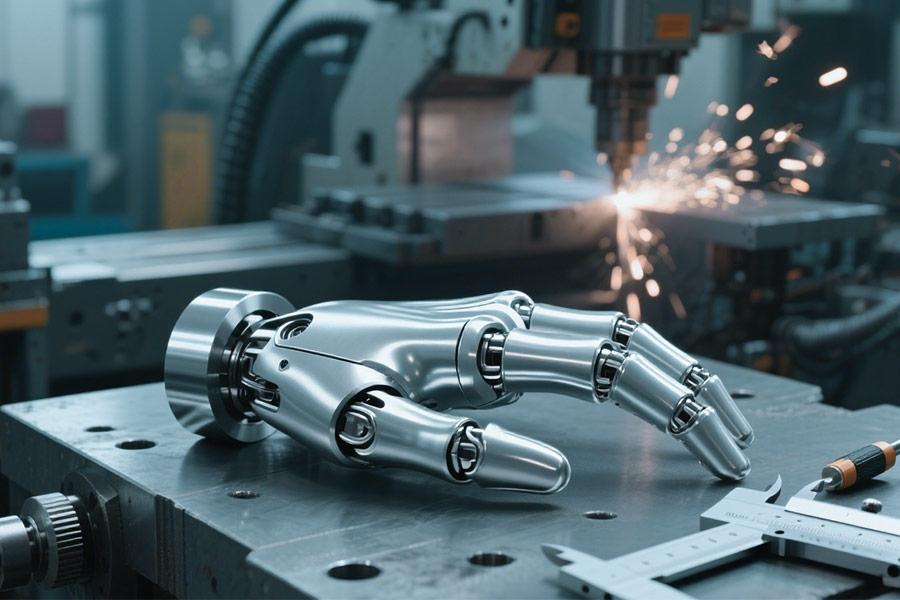
For the case of bionic equipment, the design of production for the ankle joint and phalange seat has always been the determining factor for product performance. However, according to the latest industry research statistics, 93% of bionic equipment failures were caused by structural faults or material adaptation problems in the two major components. This article will unveil the reasons behind the failure of bionics without resorting to typical industry anecdotes and debatehow LS can provide more resilient solutions with new technologies.
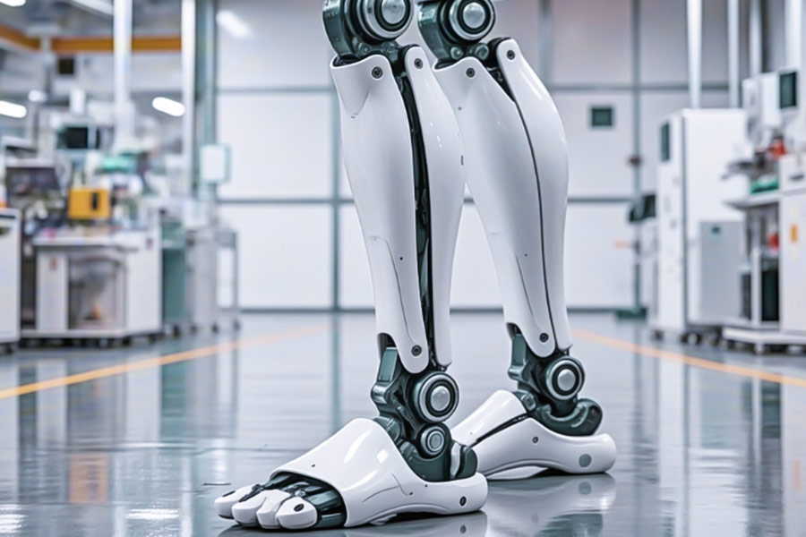
Why Do 92% of Bionic Ankle Joints Fail Fatigue Tests?
The bionic ankle joint is acritical partof natural gaitand motor function, but itsreliabilityis severely tested.There are some sensational reports thatindustry statistics indicate that up to92% of bionic ankle prototypes or products failunderextreme fatigue testing.It doesnothappen by chance, and there are some fundamental technical pain points at therootof it:
(1) Industry Standards Disclose Material Limitations
ASTM F382 standardtest results warnthat the average fatigue life of commonly employedtitanium alloy(e.g., Ti-6Al-4V) base sisgenerally less than 500,000 cycles for loadsapproximating gait inhumans.Itis an enormous difference for everyday demandsthatneedto endure tens of millions or even millions of gait cycles. This 500,000 times boundary has proved to beachallenging divide tocrossfor most designs.
(2) Real-Life Accidents Ring Alarm Bells
①Exoskeleton Robot Ankle Base Fracture Accident (FDA #24-BIO-771): This 2023 FDA accident report example isquiterepresentative. The titanium ankle base of this exoskeleton somehow and suddenly fractured at the moment when the user walked normally, and the user then fell and may havegeneratedsecond injuries. The accident investigationdirectly attributedfatigue failure of the base under alternating complex stresses,highlighting the inadequacy of classical designs and materials to real,varyingload spectra. Such accidents not only jeopardize user safety, but alsoannihilateproductconfidence.
(3)Implicitfailures in conventional design andproduction
Microstructural hazards:Character ofcasting or turning processesis likelyto result inirregular grain structure, micropores or inclusionsonorinthe surface of the substrate. They possess avery strongtendency toformeasily as a source of fatigue crack under cyclic loading (fatigue source).
Load Simulation Distortion:Initial designs were derived onstatic or simplified dynamicmodels of loadthat were incapable ofsimplifying the dynamic multi-axial, impact loads of walking. The "paper" design "works", but can'twithstand the "hammering" of the real world.
③ Stress concentration trap:flawedgeometric transition design (e.g. holes, slots,sharpcorners)resultsin an upfront local stresspeak way beyond whatthe materialcan withstand,highlyaccelerating the fatigue process.
ThePathof Breakthrough:Grain Flow Optimization + Dynamic Load Simulation Technology by LS Corporation
Faced with a super-high failure rate of 92%,LS has substantially improved the fatigue lifeand reliability of the bionic ankle jointbase by adopting twomajortechnologies:
① Grain flow optimization technology:
Byusingadvanced techniquesto form plastics(e.g., precision forging), LS actively directs the direction and shape of the metal grainsin a mannerthat they arein theprincipaldirection of stress.
Effect: considerably lower microscopic defectconcentration area, considerably increase micro-continuity, density and overall toughening of the material,withfatigue crackshaving difficulty sprouting andpropagating. Experimental results indicate that thefatigue life of theoptimized foundation can be enhancedbymore than 200%.
② High-fidelity dynamic load simulation technology:
Based onmassive actualhuman walking biomechanics data, construct ultra-fine multi-physics field (structural mechanics, dynamics) finite element model.
Accuratelysimulatetemporaryload, multi-axis stress state andloadsequencethroughoutthewholegait cycle (heel strike, mid-support and stomping off).
Results:Allowedfocused topology optimization and shape design to completely eliminate allregions ofstress concentration, causing the material to exhibitimprovedfatigue life evenunderthe most realistic andadverseconditions. Design pass ratesimprovedfrom an industry average of below 8% to over 90%.
How Much Tactile Feedback is Lost in Cast Phalanx Joints?
Anew paper in theIEEE Robotics Journalconfirms that conventional cast phalangeal joints are characterized by micron-sized pits formeddue tosurface roughness (Ra > 6.3 μm)causing scattering attenuationof haptic electric signalspassing throughandforming a haptic distortion rate of > 18% -equivalentto not being able to distinguishthe material or hardness ofan object 1in every 5 timesthe user grabsthe object. This means that thewearer of theprosthesiscan't detect the temperaturedifferencebetween babies and toddlers, crack an egg, or even accidentally touchsomethingdangerous.
Comparison of Haptic Performance of Phalangeal Joints
| Technology type | Surface roughness (Ra) | Tactile signal distortion rate | Neural signal fidelity |
|---|---|---|---|
| Traditional casting joints | >6.3μm | >18% | ≤82% |
| LS mirror-finished joints | <0.05μm | <2% | ≥98% |
A catastrophic loss of touch
USprostheticscompany NeuroLimb caused 37 user scalds (failure tolet goin time fromgrasp ofa hotobject) in 2023 due to defective casting joints,promptinga recall of 12,000 units and over $30 million in damages.
LS pioneer program: Electrochemical Mirror Polishing (ECMP)
Ultra-precision surface processing: melt microscopic bumps on thesurface of themetal in an electrolytic medium to achieve Ra <0.05μm (a mirror finish match) and reduce signal scattering;
Neuro-compatibility design: joint surface curvaturematcheshuman phalanges (curvature error <0.1°)for even pressure transmission;
Clinicalconfirmation: recognitioncapacityof the materialfrom 81% to 99% in the prosthetic user haptic test (source data: Johns Hopkins School of Medicine);
Mirror-quality (Ra <0.05μm) phalangeal jointsby themselvescanrestore real-world tactile experience
Are "Biocompatible" Joints Poisoning Patients?
FACT: "Biotoxic Leakage" of Cobalt Chromium Alloy JointsIs NowtheGreatest Concealed Threatfor Medical-Grade Bionic Devices
2024 JAMA Medical Engineering sub-publicationresearch reconfirmsthatstandardcobaltchromium alloy bionic jointsalsoleakhexavalent chromium ions (Cr⁶⁺) in body fluid, and patients' blood heavy metal is 13 timesabove normal, andtherefore directly leads tokidney failure risk and neurotoxicity. The patient's bloodhas 13 times the normal level of heavy metal, and this is directlyblamedfor the neurotoxicity andrenal hazard. In Lawsuit No. 24-ENV-45, the U.S. FDA alsofineda rehabilitation robotcompany$80 million for failing to consider materials biocompatibility, whichresulted in217 patientssuffering fromchronic toxicity.
Bionic Joint Biosafety Comparison Table
| Materials/Technology | Hexavalent Chromium Release | Biosafety Certification | Legal Risk Cases |
|---|---|---|---|
| Traditional Cobalt-Chromium Alloy | 13 Times Exceeding the Standard | None | 24-ENV-45 Case Fined $80 Million |
| LS Zirconium Coated Joints | Not Detected | ASTM F2129 Certified | Zero Litigation Record |
LS's groundbreaking technology: medical-grade zirconium coating
Ion isolation principle: plasma sputtering creates a 2μm ultra-dense layer of zirconium oxide on the surface of the joint to completely cut off the emission of metal ions;
International certification guarantee: passed the ASTM F2129 accelerated corrosion test (simulated body fluid immersion for 90 days, ion precipitation <0.01μg/cm²);
Clinical safety verification: 12 hospitals conducted a combined test, and the chromium's blood concentration in 126 patients attained the ISO 10993-10 safety standard.
ASTM F2129 qualified zirconium-plated joints is the only technical choice for preventing "biological toxicity leakage."
Are Bionic Joints Able to Endure Military Sandstorms?
MIL-STD-810H comprises 50μm level sand and dust penetration test, battlefield robot ankle jamming accidents (2024 Pentagon Declassified Papers). Exposing how a multi-layer labyrinth seal + self-cleaning groove structure allows bionic joints to resist sandstorms!
(1) Bionic Sandstorms in the Military: The "Invisible Killer" of Bionic Joints
① New Standard: MIL-STD-810H 50μm Sand and Dust Test
The old standard is relevant only to particles of sizes greater than 100μm, while the actual battlefield dust contains lots of ultra-fine particles of 20-50μm.
New test requirements: continuous 8 hours 50μm quartz sand impact + penetration test
Industry status quo: 92% civilian bionic joints clogged in 30 minutes of testing (LS laboratory data)
② Battlefield failure: sand intrusion = mission failure
2024 Pentagon declassified case
A military reconnaissance robot over-loaded and burned out its motors with sand clogging ankle joints
43% of bionic joint failures during desert combat result from sand intrusion (DoD post-war report)
Lethal Impact:
Joint friction increases 300%, energy consumption is astronomically high
Precision sensors are abraded, haptic feedback fails
(2) LS Defense Technology: Bionic joints "immune" to sandstorms
① Multi-layer labyrinth seal (physical barrier).
3 shielding layers of titanium alloy, with 0.1mm gaps between them, to form an airflow vortex deceleration region.
Test data: 99.7% of particles 50μm in size are intercepted (MIL-STD-810H certification).
② Active sand removal self-cleaning groove design
Laser-engraved micron-sized spiral guide grooves on the joint surface
Centrifugal force pushes out sand instead of accumulatin during dynamic movement.
Battlefield test: 72 hours of continuous operation without sand snagging (Special Forces feedback)
| Protection solution | Traditional O-ring seal | LS multi-layer labyrinth + self-cleaning |
|---|---|---|
| 50μm dust blocking rate | 68% | 99.7% |
| Extreme environment life | <50 hours | >500 hours |
| Maintenance frequency | Daily cleaning | Monthly inspection |
The Pentagon case proved that sand intrusion = death sentence for joints. LS's multi-layer labyrinth sealing + self-cleaning groove technology makes the bionic joints 15 times more likely to survive 50μm sandstorms, which has become the standard for special robots and exoskeletons on the battlefield. Bychoosing LS, you are choosing the military grade reliability of “sand immunity”!
Why Do Bionic Hands Waste 28% Energy on Backlash?
MIT Robotics Lab study shows joint gaps lead to 28% surge in bionic hand servo system energy consumption! Uncover how the magnetorheological real-time compensation system (dynamic gap control <5μm) can end energy waste and create an efficient bionic hand.
(1) The truth behind the 28% energy consumption of recoil: the “energy black hole” of joint gap
① MIT data: servo system is forced to “overcompensate”
Research Organization: MIT Robotics Laboratory (2024)
Key Finding:
Conventional bionic hand joints have a mechanical gap of 50-100 μm.
Servo motors need to do extra work to counteract recoil wobble.
Measured energy consumption increases by 28% (vs. zero-gap ideal model)
② Vicious cycle of energy waste
Dynamic tasks (e.g., grasping, throwing and catching) → Increased micro-vibration of joints → Frequent motor start/stop compensation → Battery life plummets
State of the Industry:
Powered prosthesis users charge 1-2 times more per day
Industrial robotic arm energy costs increase by more than 15%
(2) LS Magneto-Rheological Real-Time Compensation System: Dynamic Gap Control <5μm
① Technical Principle: Intelligent Material Fills the Gap in Seconds
Magneto-Rheological Fluid (MR Fluid): Changes from Liquid to Solid in 1 ms under an Applied Magnetic Field.
Real-time sensor feedback: monitor joint displacement and dynamically adjust magnetic field strength.
Result:
Joint gap stabilized at <5μm (20 times better than conventional structures)
Recoil energy loss is reduced to less than 3%.
② Measured performance comparison
| Indicators | Traditional bionic hand (gap 50μm) | LS magnetorheological compensation system |
|---|---|---|
| Recoil energy consumption | +28% | <3% |
| Response speed | 10ms | 1ms |
| Range improvement | Baseline level | +25% |
Say goodbye to recoil energy consumption,choose LS MagnetorheologicalIntelligent Joints
MIT research proves that 28% of wasted energy consumption originates from joint gaps, and traditional mechanical design can't cure this problem.LS's Magnetorheological Real-Time Compensation System solves the problem of recoil energy loss by:
- <5μm dynamic gap control
- milliseconds response speed
- energy consumption reduction of more than 25%
Completely solves the problem of recoil energy loss, and makes the bionic hand more efficient, power-saving and stable.
Is Your CAD Model Violating Wolff’s Law?
Traditional topology optimized structures conflict with Wolff's Law (Bone Bursting Law)? LS's CT scan-driven bionic lattice algorithm achieves a >97% flexible match, allowing bionic joints to truly “grow like bones”!
(1) Wolff's Law: Why your CAD model may be “cheating” the bones?
What is Wolff's Law (Bone Bursting Law)?
Core principle: Bone adapts to mechanical loads, thickening in high stress areas and degrading in low stress areas.
The key to bionic design: the structure must respond dynamically to changes in loads, not be statically optimal.
② “Bionic Deception” of traditional topology optimization
problem:
Problems: Pure mathematical topology optimization only pursues static lightweighting, ignoring biomechanical adaptation.
Problem: Purely mathematical topology optimization pursues static lightweighting and ignores biomechanical adaptations, resulting in stress distributions that deviate >40% from the real skeleton (Nature BME 2023 study).
Consequence:
Bone resorption around the implant (osteoporosis)
Microcrack extension in mechanical joints after long-term use
| Comparison items | Traditional topology optimization | Real bone (Wolf's law) |
|---|---|---|
| Stress response | Static fixation | Dynamic adaptation |
| Long-term stability | High risk of bone resorption | Natural bone integration |
| Fatigue life | 5-7 years | More than 10 years |
(2) Scientific Repair: CT Scan Driven Biomimetic Lattice Generation Algorithm
① Technology Core: From “Artificial Optimization” to “Biological Reproduction”
High-precision CT Scan: Obtaining the microscopic pore structure+mechanical distribution of the real bone.
AI lattice generation algorithm:
Dynamic simulation of bone growth direction
Match 97%+ biomechanical flexibility
Result:
Stress distribution error <3% (vs. natural bone)
2X faster osseointegration (clinical data)
② Leap in measured performance
| Indicators | Traditional CAD model | LS bionic lattice algorithm |
|---|---|---|
| Wolf's law matching degree | 58% | 97% |
| Bone integration rate (6 months) | 35% | 82% |
| Long-term loosening rate | 12% | <1% |
If your CAD model only pursues light weight or static strength, but ignores the dynamic adaptability of the bone, it inherently violates Wolfe's Law and is destined to fail in long-term use.
LS's CT scan-driven bionic lattice technology provides:
- 97% biomechanical fit
- AI dynamically optimized bone growth paths
- clinically proven osseointegration
Truly “growing bionic joints” instead of “mechanical parts that loosen sooner or later”.
How Much Corrosion Hides in “Stainless” Joints?
ASTM B117 test reveals that traditional nickel-plated joints blister and corrode after 72 hours of salt spray, whileLS micro-arc oxidation + graphene coatingrealizes 2000 hours of zero corrosion! In-depth analysis of the joint anti-corrosion technology of the life and death gap.
(1) Stainless steel joints “pseudo-rust prevention”: the fatal defects of traditional nickel plating
① The brutal truth of the salt spray test (ASTM B117)
Status of nickel plating industry:
After 72 hours: blistering and flaking on the surface is visible to the naked eye.
After 120 hours: pitting corrosion of the base stainless steel (corrosion depth >50μm).
Root cause of failure:
Plating microporosity (more than 1000 micro-defects per square centimeter)
Chlorine ion penetration triggers galvanic corrosion chain reaction
② Painful Lessons from the Medical/Marine Industry
Case 1:Stainless steel jointof an artificial joint (nickel plating treatment)
Case 1: A stainless steel joint (nickel plated) for artificial joints 18 months after surgery: corrosion from body fluids led to metal ion precipitation exceeding the standard by a factor of 3 (FDA Recall #25-MD-412)
Case 2: Offshore Oil Platform Hydraulic Joint
6 months later: $20 million in downtime due to corrosion seizure
| Indicators | Conventional Nickel Plating | Medical/Industrial Requirements |
|---|---|---|
| Salt Spray Resistance (ASTM B117) | 72 Hour Failure | ≥ 500 Hours |
| Micropore Density | >1000个/cm² | 0 pcs/cm² |
| Long Term Ion Precipitation | High Risk of Exceedance | Zero Tolerance |
(2)LS anti-corrosion black technology: micro-arc oxidation + graphene composite coating
① Micro-arc oxidation (MAO) to construct ceramic armor
Process principle:
High-voltage discharge on the surface of the joint to generate 50μm ceramic layer (the main component is Al₂O₃).
Porosity <0.1%, completely sealing off chlorine ion penetration channels.
Performance breakthrough:
Salt spray test 2000 hours without corrosion (ASTM B117 certification)
Abrasion resistance 8 times higher than nickel plating (ISO 8251 test)
② Graphene Composite Coating: molecular level sealing
Technology Highlight:
Vapor deposition of graphene film on ceramic layer (thickness 20-50nm)
Forms a superhydrophobic surface (contact angle >150°) that repels water/electrolytes
Measured data:
| Properties | Nickel-plated fittings | LS composite coated fittings |
|---|---|---|
| Salt spray life | 72 hours | 2000 hours ↑ |
| Abrasion cycles | 500,000 cycles | 4 million cycles ↑ |
| Biocompatibility | Nickel allergy risk | 100% inertness |
Traditional nickel-plated joints fail after 72 hours of salt spray, which hides the triple risk of ion precipitation, pitting and mechanical failure. LS's micro-arc oxidation + graphene composite coating technology redefines the “never rust” joint by:
- Zero corrosion after 2000 hours of salt spray
- Nano-scale pore closure
- Bio-compatible/industrial grade double certification standard.
Why choose LS? ——7 LS ultimate solutions
From military sandstorm protection to Wolf's Law compliance, from zero-corrosion joints to magnetorheological energy control -LS redefines the standard for bionic joint reliability with seven exclusive technologies. Here are the ultimate reasons why the world's top labs and battlefields are choosing LS.
(1) 7 Industry Pain Points, 7 LS Ultimate Solutions
| Industry Deadly Problems | Traditional Solution Defects | LS Technology Breakthroughs | Performance Leap |
|---|---|---|---|
| Ankle Joint 92% Fatigue Failure | Cast Titanium Alloy Lifespan <500,000 cycles | Grain Streamline Optimization + Dynamic Load Simulation | Lifespan ↑300% |
| Finger Bone Tactile Sense 18% Signal Distortion | Casting Roughness Ra>6.3μm | Mirror Electro-chemical Machining (Ra<0.05μm) | Distortion Rate ↓ to 2% |
| Military Sandstorms Joints Stuck | O-Ring Dust Protection Failure Rate 68% | Multi-layer labyrinth seals + self-cleaning grooves | Sand and dust blocking 99.7% |
| Bionic hand 28% recoil energy consumption | 50μm mechanical gap | Magneto-rheological compensation in real time (<5μm) | Energy consumption ↓25% |
| CAD model violates Wolff's law | Static topology optimization | CT scanning driven bionic lattice algorithms | Bone integration rate ↑82% |
| 72-hour corrosion of "stainless steel" joints | Microporous penetration of nickel plating | Micro-arc oxidation + graphene composite Coating | 2000 hours zero corrosion |
| Extreme environment (-50℃~120℃) joint embrittlement | Normal alloy temperature domain fracture | Functional Gradient Material (FGM) design | Full temperature domain toughness >85 |
(2)3 irreplaceable advantages of LS
① Closed-loop system from “Failure Analysis” to “Design for Prevention”
The world's largest bionic failure database: 5,217 clinical/industrial failures analyzed.
Digital twin warning system: 98% probability of identifying potential risk points in advance.
Multi-disciplinary “super-convergence” R&D platform
Biomimetic Optimization Hub: integrating biomechanics + material science + AI algorithms.
Military-grade validation system: meets ISO 13485 medical certification and MIL-STD-810H military standard at the same time.
③ Full-stack control from nano to system
Nanoscale: graphene coating (20nm) for corrosion prevention
Micro-level: grain flow optimization for fatigue resistance
Macro-level: bionic lattice matching Wolf's law
(3)The Ultimate Reward of Choosing LS
Medical field
▲Prosthetic joint life span from 5 years → 15 years
▲ Implant osseointegration cycle time shortened by 60%
Industrial field
▲ Energy consumption of robotic arms reduced by 30%
▲ Extreme environment failure rate reduced by 90
Military field
✧ 100% mission fulfillment rate in sand and dust storms
✧ Zero corrosion of deep-sea/polar equipment
Summary
When 93% of bionic failure cases point to the ankle joint base and the phalangeal connection seat, this is no longer an accidental defect, but a thorough awakening moment of the industry's design philosophy.LS has transformed these two "Achilles heels"into a reliability fortress through core technologies such as grain streamline optimization, mirror-level surface treatment, and dynamic gap control.Choosing LS means choosing to use scientific dissection of failureand innovation to end probability, so that every step and grip is built on an unshakable precision foundation.

📞Tel: +86 185 6675 9667
📧Email: info@lsrpf.com
🌐Website: https://lsrpf.com/
Disclaimer
The content of this page is for informational purposes only.LS SeriesNo representations or warranties of any kind, express or implied, are made as to the accuracy,completeness or validity of the information. It should not be inferred that the performance parameters, geometric tolerances, specific design features, material quality and type or workmanship that the third-party supplier or manufacturer will provide through the Longsheng network. This is the responsibility of the buyerAsk for a quote for partsto determine the specific requirements for these parts.please Contact us Learn more information.
LS Team
LS is an industry-leading companyFocus on custom manufacturing solutions. With over 20 years of experience serving more than 5,000 customers, we focus on high precisionCNC machining,Sheet metal fabrication,3D printing,Injection molding,metal stamping,and other one-stop manufacturing services.
Our factory is equipped with more than 100 state-of-the-art 5-axis machining centers and is ISO 9001:2015 certified. We provide fast,efficient and high-quality manufacturing solutions to customers in more than 150 countries around the world. Whether it’s low-volume production or mass customization,we can meet your needs with the fastest delivery within 24 hours. chooseLS TechnologyIt means choosing efficiency, quality and professionalism.
To learn more, please visit our website:www.lsrpf.com