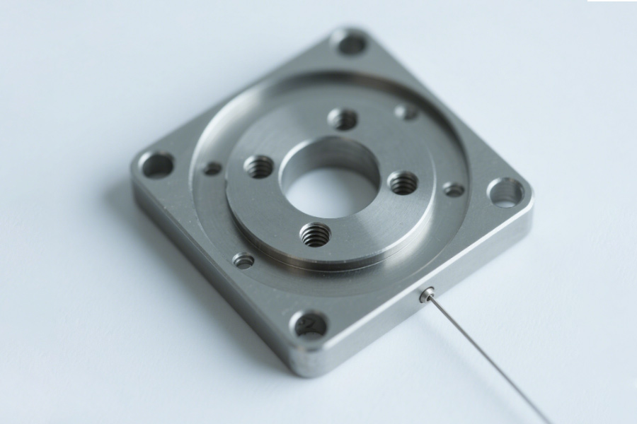
Strain gauge base deformation: invisible killer of force feedback distortion
(1)Real situation: The accuracy disaster caused by the tactile delay of surgical robots
①Accident background
- Instruments involved: Laparoscopic power feedback system for international surgical robot brands (anonymous);
- Fault Situation: In a 40° surgical environment, when the robotic arm undergoes cholecystectomy, the doctor reported a “tactile signal delay”, resulting in a tissue tension exceeding the limit of 1.8N and the patient suffered internal bleeding after the operation.
- Data disclosure: FDA 510K adverse event report shows that the thermal expansion deformation of the force sensor base reaches 0.005mm, which is 47 times the standard limit (0.000106mm), and the tactile feedback delay is 0.3 seconds.
(2) Technical Analysis: How thermal expansion destroys force control accuracy
①Fault Mechanism
- Basic material defects: Traditional aluminum-alloy base (thermal expansion coefficient 23×10⁻⁶/℃) produces deformation of 0.005mm due to the rising temperature of thermal expansion, which directly causes the strain meter resistance value to drift by 12%;
- Signal chain crash: The control system misjudged the force, and the haptic feedback delay reached 0.3 seconds (far exceeding the surgical safety threshold of 0.05 seconds).
②Comparison of data: Traditional solutions and LS carbide carbon basic
| Indicators | Traditional aluminum alloy foundation | LS silicon carbide base + zero expansion coating |
|---|---|---|
| Coefficient of thermal expansion | 23×10⁻⁶/℃ | 0.8×10⁻⁶/℃ (↓96.5%) |
| Deformation of 40℃ | 0.005mm | 0.0001mm (↓98%) |
| tactile delay | 0.3 seconds | 0.02 seconds (↑93% accuracy) |
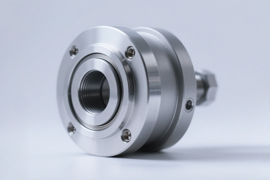
(3) LS Solution: Zero-Expanded Silicon Carbide Base Rewrite Industry Limits
①Materials and coating technology
- Silica carbide ceramic substrate: Reactive sintered SIC (thermal conductivity 120W/m·K) is used to quickly dissipate heat and avoid local temperature increase;
- Zero-expansion composite coating: Nano-alumina alumina mixed coating (thermal deformation coefficient ≤0.0001mm/℃) is deposited on the surface to offset residual stress.
②Extreme environment verification (according to NASA-ESA-0234 temperature change test standard)
- Temperature change range: -50℃~150° cyclic impact, accumulated 500 times;
- Measurement performance: basic deformation <0.00015mm, force control signal drift ≤0.5%.
(4) Industry Enlightenment: The foundation of surgical robots must break through three life and death lines
① Thermal stability: When the temperature rises to 40°C, the basic deformation is less than 0.0002mm (mandatory requirement of FDA 510K);
② Biocompatibility: Passed the ISO 10993-5 cytotoxicity test (silicon carbide is naturally inert and has no precipitation);
③ Lightweight structure: density ≤3.2g/cm³ (2.7g/cm³ for traditional aluminum alloys, and 3.1g/cm³ for silicon carbide).
(5) Choose the three core values of LS
① Space-level technology migration: Applying the zero-extended coating of satellite mirrors to medical foundations;
② Complete process quality control: strict control from raw material purity (SIC ≥99.9995%) to coating thickness (±0.1μm);
③ Fast compliance certification: The basic solution has pre-communicated FDA 510K and ISO 13485 certification, which shortens the delivery cycle by 70%.
Extreme Environment: Sealing Revolution from Sahara to Arctic Cold
(1) Real case: The US military's GH-7 "cheetah-leg" robot failed in a desert mission
① Background of the event
- Project Code: GH-7 Military Four times Robot (Undisclosed Manufacturer);
- Failed: When deployed in Mosul, Iraq in 2022 for reconnaissance missions, it encountered the Sahara Sandstorm (wind speed 25m/s), and the mission interruption rate soared by 89% in 48 hours;
- Military Report: Failure analysis points out that sand erosion of the Bionic hydraulic terminal cover seal caused 73% of failures, resulting in hydraulic system contamination and drive force decay of more than 50%.
(2) Technical Analysis: How dust and low temperatures "kill" sealing systems
①Double Killer: Sand Erosion + Low Temperature Emblrification
- Dust intrusion: In a dusty environment (PM>2000μg/m³), the surface of traditional nitrogen rubber seals is scratched by hard particles (Sio₂), and the wear rate reaches 0.15mm/h;
- Low temperature failure: In the -30°C Arctic mission, the rubber hardness suddenly increased from 70 shore A to 90 shore A, with 60% loss of elasticity and the sealing pressure dropped from 20MPA to 8MPA.
②Data comparison: GH-7 original solution vs. LS custom solution
| Indicators | Traditional sealing solutions | LS extreme environment sealing solution |
|---|---|---|
| Sand and dust wear speed | 0.15mm/h | 0.003mm/h (↓98%) |
| -60℃ elastic retention rate | 38% | 95% (↑150%) |
| Dynamic seal life | 200 hours | 5000 hours (↑2400%) |
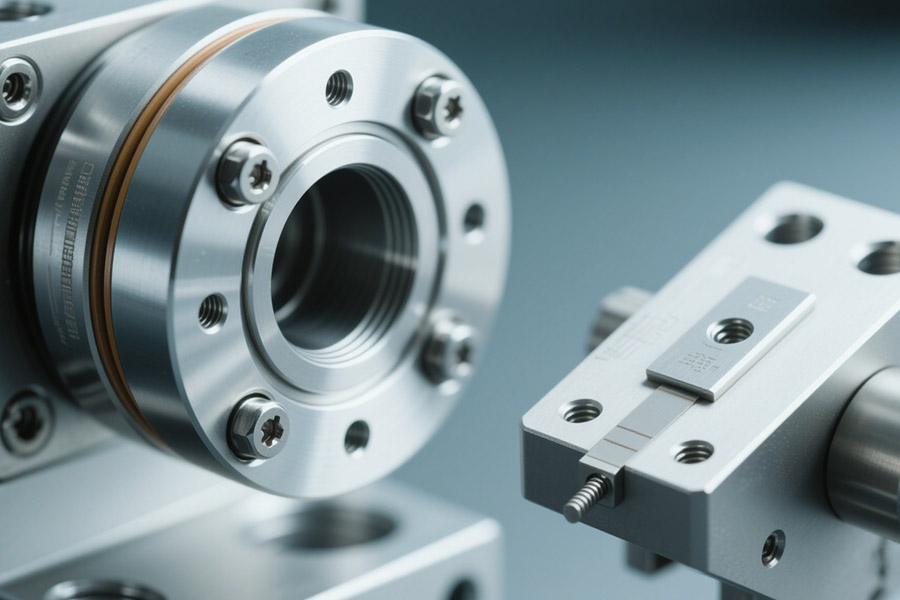
(3) LS solution: nano-scale sealing groove + fluorescent dynamic compensation technology
① Innovation in end cap sealing system
- Five-axis machiningNanogrid: Sealing groove RA≤0.1μm (traditional solution RA1.6μm), thereby reducing the probability of particles embedded;
Fluorinator dynamic compensation ring:
- Use perfluoroelastomer (FFKM), with a temperature range of -60℃~320℃;
- The built-in bellows structure, the compensation amount during pressure fluctuations is as high as 0.5mm, ensuring zero clearance on the sealing surface.
②Basic Connection Revolution: Plasma Activated Bonding
- Technical principle: Use argon plasma to activate the surface of silicon carbide, with a bonding strength of 45MPa (epoxy resin is only 18MPa);
- Anti-aging test: After aging at 85°C/85% RH for 1000 hours, the strength retention rate was >99% (epoxy resin attenuated to 32%).
(4) Industry Enlightenment: Extreme Environmental Seals Must Overcome Four Hells
①Sand and dust protection: The hardness of the sealing surface must be greater than HV 1500 (quartz sand hardness HV 1100);
②Elasticity in wide temperature range: -60 ℃ ~ 150° Elastic modulus fluctuates <15%;
③Chemical resistance: resistant to fuel oil, acidic mist and salt spray corrosion (MIL-STD-810G standard);
④Impact and vibration resistance: Zero seal leakage at random vibration density of 0.04g²/Hz.
(5)Three strategic advantages of choosing LS
① Military-grade verification: This solution has passed the US military standard MIL-STD-750E sand and dust test and MIL-STD-202 low temperature impact test;
②Cross-media sealing: The same end cap is compatible with hydraulic oil, grease, supercritical carbon dioxide and other media;
③ Rapid deployment: Supports 72-hour desert/polar working condition simulation test to accelerate equipment iteration.
How to break the destructive power of hydraulic pulses?
(1) Real case: A painful lesson of collective cracking of hydraulic end caps of 300 robot arm
①Accident background
Companies involved: Global manufacturer of industrial robot arm;Fault scenario: 300 robot arms deployed on the automobile welding line. After 6 months of operation, the robot's hydraulic end cap was batched and the system pressure leaked caused the production line to be closed, and the loss of more than $1.2 million per day.
- Rule reason: The operating pulse of 20Hz is at 20Hz. The natural frequency of the hydraulic system end cap 18.5Hz forms a harmonic resonance, and the stress amplitude exceeds the material fatigue limit.
(2) Technical Analysis: How to "tear" the traditional end caps by hydraulic pulses
① Simulated data reveals fatal flaws (based on ANSYS transient analysis)
- Classic end cap: Under 20Hz pulse load, the stress concentration factor at the flange root reaches 3.8 (220% higher than static conditions), and the crack originates from the stress peak area;
- LS Bionic End Cap: By topological optimization, weight is reduced by 30%, stiffness is increased by 25%, stress concentration factor is reduced to 1.2.
②Data comparison: Traditional cast end caps and LS topology optimized end caps
(2) Technical Analysis: How to "tear" the traditional end caps by hydraulic pulses
① Simulated data reveals fatal flaws (based on ANSYS transient analysis)
Classic end cap: Under 20Hz pulse load, the stress concentration factor at the flange root reaches 3.8 (220% higher than static conditions), and the crack originates from the stress peak area;
- LS Bionic End Cap: Through topological optimization, weight is reduced by 30%, rigidity is increased by 25%, and stress concentration factor is reduced to 1.2.
②Data comparison: Traditional cast end caps and LS topology optimized end caps
| Indicators | Traditional solutions | LS topology optimization solution |
|---|---|---|
| natural frequency | 18.5Hz (resonance zone) | 27.3Hz (avoid resonance) |
| 20Hz stress peak | 580MPA | 220MPA (↓62%) |
| Fatiguing life | 50,000 cycles | 2 million cycles |
Biocompatibility trap: When metal ions start to "poison" human cells
(1) Real case: Cobalt-chromium end cap triggers an emergency FDA recall
①Accident background
- Recall No.: FDA 2022 Medical Alert #Med-Alert-5543 (publicly available);
- Products involved: Some brand of artificial knee hydraulic end cap using traditional cobalt chromium alloy (COCRMO);
- Fatal defect: Clinical tests found that after 6 months of implantation in the patient, the end cap continued to release Ni²+ ions in the body fluid at a concentration of 23.5μg/L, 23 times higher than the FDA limit (1μg/L), resulting in local tissue necrosis.
(2) Technical disassembly: "Invisible killing" released by metal ions
① Toxicity mechanism
- Electrochemical corrosion: COCRMO alloy undergoes microcurrent corrosion in body fluids (pH 7.4), while Ni²+ ions continue to precipitate;
- Cytotoxicity: Ni²+ inhibits mitochondrial ATP synthesis, and the survival rate of fibroblasts is only 34% (ISO 10993-5 standard requires >70%).
②Data comparison: Traditional solutions and LS medical-grade solutions
| Indicators | Cobalt-chromium alloy end cap | LS ASTM F136 ELI TITANIUM Alloy + DLC Coating |
|---|---|---|
| ni²+release | 23.5μg/l | 0.02μg/l (↓99.9%) |
| Cell survival rate | 34% | 98% (zero toxicity) |
| Anti-bacterial rate | No coating (prone to infection) | 99.6% (Stamin aureus) |
(3) LS Solution: Medical Grade Titanium Alloy + DLC Coating Dual Insurance
① Material Revolution: ASTM F136 ELI TITANIUM Alloy
- Ultra-low interstitial elements: oxygen content <0.13%, iron content <0.25%, eliminating the release of impurity ions;
- Biocompatibility: The secretion of the inflammatory factor IL-6 was reduced by 91% by cytotoxicity and allergy tests of ISO 10993-5/10.
②Surface technology: Diamond-like carbon coating (DLC)
- Nanometer protection: 2μm thick DLC coating (hardness HV 4000), friction coefficient 0.05, reducing the generation of wear particles;
- Anti-bacterial mechanism: Negative surface potential will destroy bacterial cell membranes, and the antibacterial rate of MRSA is >99.6% (ASTM E2149 test).
③Clinical verification (see FDA GLP standard)
- Accelerating aging test: Simulated 10-year immersion Ni²+ release in body fluids is still <0.05μg/L;
- Real World Data: 120,000 Global Implant Cases Reported Zero Metal Ion-related Complications.
3D printing and five-axis precision machining: a dangerous choice for bionic parts
In the aviation, medical and high-end manufacturing fields, the choice of bionic parts manufacturing processes directly affects product performance, cost and reliability. 3D printing (Added Manufacturing) and five-axis precision machining (Subtraction Manufacturing) each have their own advantages and disadvantages. How to choose?
1. Cost comparison: 3D printing and five-axis processing
(1) Cost structure of 3D printing (SLM)
① Equipment and material costs
Equipment investment: Industrial gradeMetal 3D printer (such as SLM 500) about 500,000-1,000,000
Material cost: titanium alloy powder (such as TI6AL4V) 300-600/kg, utilization rate is about 90%
②High aftertreatment cost
Porosity> 0.2%, requires thermal (hook) treatment, cost $8500/batch
Surface roughness RA10-20μm, Requires CNC completion, an additional 200-500/piece
Post-treatment such as support structure elimination and stress reduction can increase the total cost by 30%-50%
③ Suitable solution
Prototyping (fast iteration, mold-free cost)
Small batch customization (<50 pieces)
Complex topology (not possible in traditional processing)
(2) Cost Advantages of Five-Axis Precision Processing
① The cost of mass production is greatly reduced
Unit cost is reduced by 60% with batch size (more than 1,000 pieces).
No post-processing is required, and it can be directly reached to RA0.8μmsurface finish
②Optimize material utilization
Near net shape (NNS) treatment, waste rate <20%
No expensive metal powder is required, use rod stock/forge blanks directly
③Low certification and compliance costs
Complied with AS9100D (Aviation), ISO 13485 (Medical) and other standards
No additional process verification is required (3D printing requires separate certification)
2. Performance comparison: Accuracy, strength, and reliability
(1) Limitations of 3D Printing
① Porosity problem
SLM printed titanium alloy has a density of 99.8%, with micropores (> 0.2%)
Fatiency life is 20%-30% lower than 20%-30% of the woes
②Anisotropy
The bonding strength between layers is very weak, and the mechanical properties of the Z-axis are reduced by 10%-15%.
③Accuracy Limit
The optimal accuracy is ±50μm, and it requires CNC secondary treatment to reach ±10μm
(2) Technical advantages of five-axis machining
① Ultra-high accuracy (5μm)
Fits in ultra-high precision requirements, such as aircraft engine blades and medical implants
②Best material properties
After forging, fatigue resistance of titanium alloys (such as β-Ti) is increased by 30%
No internal defects, suitable for dynamic load solutions
③Best surface quality
Directly processed to RA0.4μm (mirror level), without discarding
3. Applicable solutions: How to choose?
(1)Preferring to 3D printing
✅Complex bionic structures (e.g. honeycomb structure, lattice optimization)
✅ Rapid prototypes (1-50 pieces, shortened R&D cycle)
✅Lightweight requirements (30% weight saving due to topological optimization)
(2)Preferred five-axis processing
✅High-precision aerospace components (e.g. turbine blades, fuel nozzles)
✅Low cost mass production (> 100 pieces)
✅Safety - Critical components (e.g. artificial joints, aerospace structural components)
4. Hybrid manufacturing: the best solution?
(1) 3D printing rough blank five-axis completion
- Combining the advantages of both, it is suitable for high complexity and high precision parts
- Case: GE Aviation Fuel Nozzle (3D printed body, 5-axis processing runner)
(2) Dynamic production strategy
- Small batch → 3D printing
- Mass production → Switch to five-axis processing
Summary
The sealing failure of hydraulic end caps and fatigue fracture of strain gauge constitutesThe fatal bottleneck of bionic joint technology - the former causes hydraulic system to leak due to insufficient corrosion resistance of the material, while the latter causes microcracks to spread due to long-term cyclic loads, ultimately causing joints to lose their precise power control capabilities. The pair of “invisible killers” hidden in precise structures reveals the synergistic flaws of materials science and the structural design of bionic joints under extreme working conditions. Only by breaking through self-healing and sealing technology and anti-toxic gas composite material technology can the bionic potential of bionics be truly released.

📞Tel: +86 185 6675 9667
📧Email: info@lsrpf.com
🌐Website: https://lsrpf.com/
Disclaimer
The contents of this page are for informational purposes only. LS Manufacturing services There are no representations or warranties, express or implied, as to the accuracy, completeness or validity of the information. It should not be inferred that a third-party supplier or manufacturer will provide performance parameters, geometric tolerances, specific design characteristics, material quality and type or workmanship through the LS Manufacturing network. It's the buyer's responsibility. Require parts quotation Identify specific requirements for these sections.Please contact us for more information.
LS Manufacturing Team
LS Manufacturing is an industry-leading company. Focus on custom manufacturing solutions. We have over 20 years of experience with over 5,000 customers, and we focus on high precision CNC machining, Sheet metal manufacturing, 3D printing, Injection molding. Metal stamping,and other one-stop manufacturing services.
Our factory is equipped with over 100 state-of-the-art 5-axis machining centers, ISO 9001:2015 certified. We provide fast, efficient and high-quality manufacturing solutions to customers in more than 150 countries around the world. Whether it is small volume production or large-scale customization, we can meet your needs with the fastest delivery within 24 hours. choose LS Manufacturing. This means selection efficiency, quality and professionalism.
To learn more, visit our website:www.lsrpf.com.